
Brushless DC Motor (BLDC) Working Principle Explained: Differences from Brushed Motors and PMSM, and Selection
The essence of a brushless motor (BLDC) is using electronic switches + rotor position detection to replace the pair of wearing carbon brushes and commutator in a brushed DC motor. The motor body itself did not become more complex — the controller did. And it is precisely this "complexity" that brings order-of-magnitude improvements in life, efficiency, and power density.
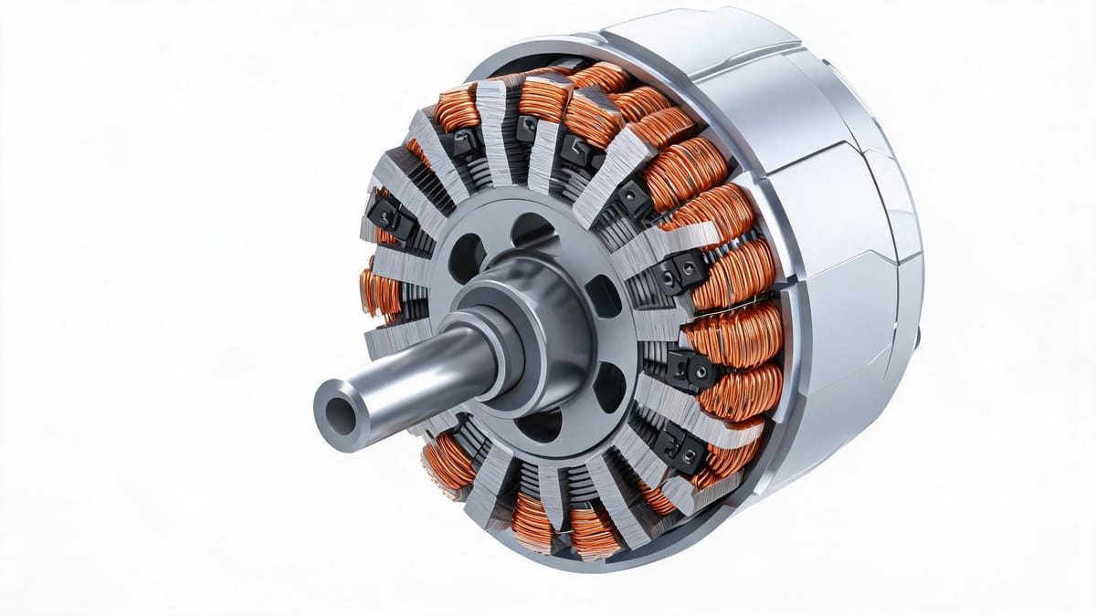
Figure: Brushless DC motor cutaway — permanent magnet rotor, three-phase stator windings and Hall sensors at a glance
1. Starting from the Brushed Motor: Why "Brushless"
How a Brushed DC Motor Rotates
The structure of a brushed DC motor (Brushed DC Motor) is:
Stator: permanent magnet, providing a fixed magnetic field;
Rotor: winding (armature), energized to rotate under the force of the magnetic field;
Commutation device: carbon brushes + mechanical commutator.
The rotor winding rotates with the rotor; without commutation, after the winding passes 180° the direction of the force would reverse, and the motor would swing back and forth instead of rotating continuously. The commutator reverses the current direction the moment the winding crosses the neutral plane, keeping the torque direction consistent.
The Three Fatal Weaknesses of the Brushed Structure
Weakness | Consequence |
|---|---|
Carbon brush mechanical friction | Wear produces carbon dust, limited life (typically 1000–3000 hours), requires periodic replacement |
Commutation sparks | Produce electromagnetic interference (EMI), a safety hazard in flammable/explosive environments |
Contact resistance and voltage drop | Efficiency loss; heat concentrated in the rotor (hard to dissipate) |
A brushless motor solves all these weaknesses at once: move the permanent magnet to the rotor, put the winding on the stator (much easier to cool), and hand commutation over to electronic circuitry.
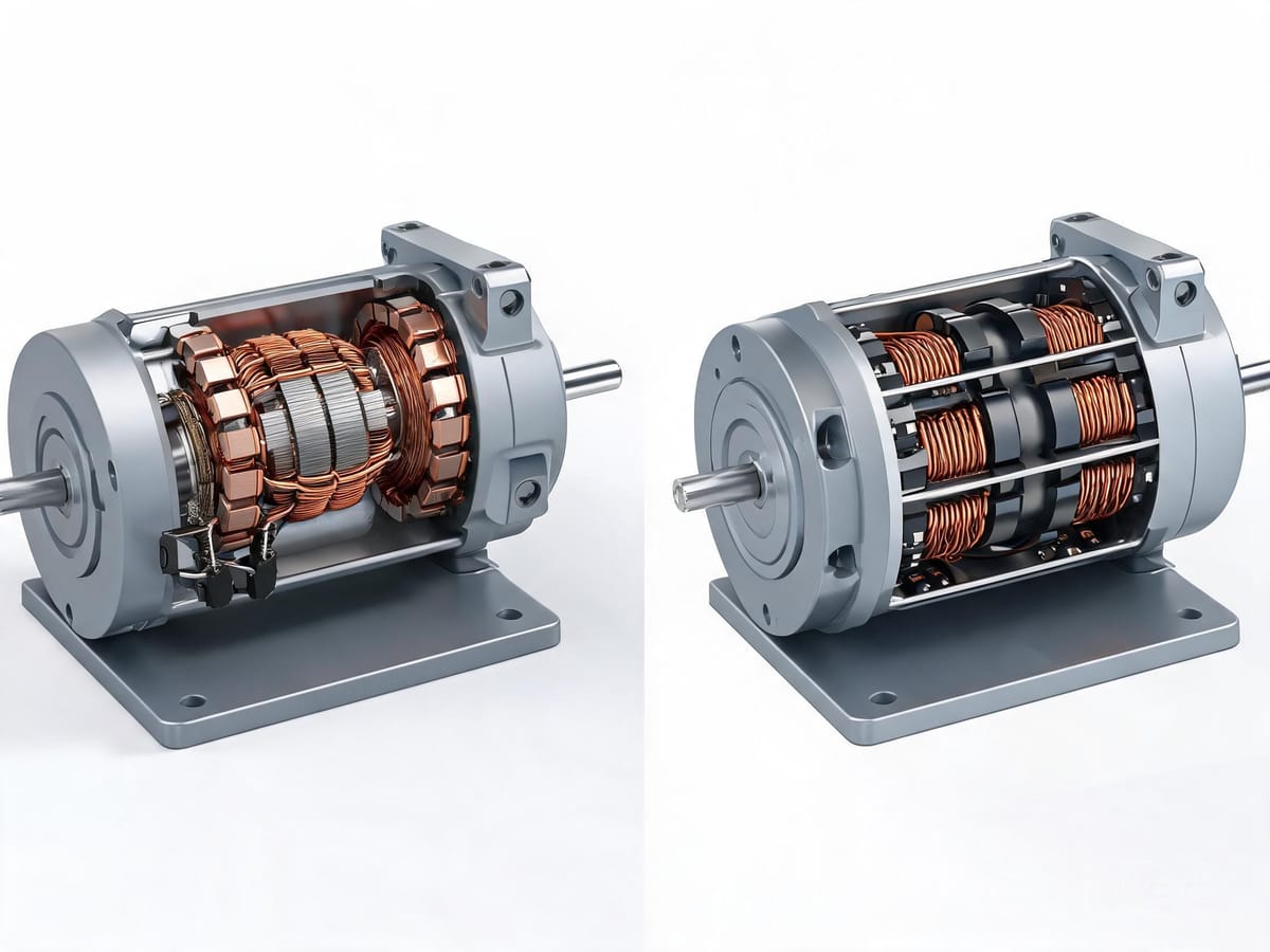
Figure: Internal structure comparison between a brushed motor (carbon brushes + commutator) and a brushless motor (electronic commutation)
2. How Does a BLDC Rotate
Basic Construction
Part | Description |
|---|---|
Rotor | Permanent magnet (surface-mounted rare-earth magnets), commonly 2–8 pole pairs |
Stator | Three-phase winding (commonly Y-connected), using concentrated windings |
Position sensor | 3 Hall elements (Hall Sensors), arranged 120° electrical degrees apart; or a sensorless solution |
Controller | Three-phase inverter bridge (6 power transistors) + control logic |
Electronic Commutation: Six-Step Commutation
The most classic control method for BLDC is six-step square-wave drive (Six-Step / Trapezoidal Commutation):
Three Hall sensors detect the rotor magnet pole position and output 6 state combinations (changing every 60° electrical degrees);
The controller decides which two phases of the three-phase winding to energize based on the Hall state;
It uses two-phase-on conduction: each phase conducts for 120° electrical degrees, with commutation every 60° electrical degrees;
The stator produces a stepping rotating magnetic field, and the rotor permanent magnet follows.
Key point: BLDC only needs to know the commutation point position (once every 60°), not continuous precise angles. This is why it commonly uses low-cost Hall sensors instead of expensive encoders.
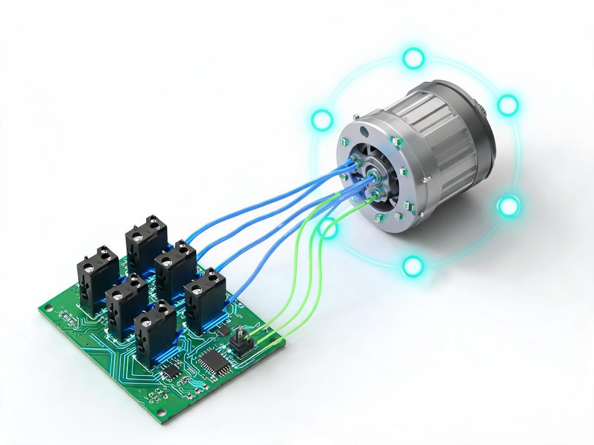
Figure: BLDC six-step electronic commutation — the three-phase inverter energizes the windings two at a time according to the Hall signal sequence
Back-EMF: Trapezoidal Wave
When the winding rotates in the magnetic field, it generates an induced EMF opposite in direction to the external voltage, called back-EMF. The BLDC's magnetic circuit design produces a trapezoidal flux density distribution in the air gap, so the back-EMF waveform is a trapezoidal wave.
This is also the most fundamental electromagnetic difference between BLDC and PMSM — see Chapter 4 below.
Sensorless Control
Hall sensors add cost, size, and failure points. Therefore it is possible to omit the sensors and infer the rotor position by detecting the back-EMF zero-crossing of the non-conducting phase.
The cost: when the motor is stationary there is no back-EMF, so sensorless solutions have difficulty starting and poor low-speed performance. Therefore:
Fans, pumps, drones (no high requirement for starting smoothness) → sensorless;
Applications needing low-speed high torque, frequent start/stop, or starting under load → must use Hall sensors or an encoder.
3. BLDC vs Brushed DC Motor
Comparison Item | Brushed DC Motor | Brushless DC Motor (BLDC) |
|---|---|---|
Commutation method | Mechanical (brushes + commutator) | Electronic (inverter bridge) |
Magnetic field position | Stator permanent magnet, rotor winding | Rotor permanent magnet, stator winding |
Life | Limited by brush wear, 1000–3000 h | Limited only by bearings, up to 20000 h+ |
Efficiency | 75%–80% | 85%–90%+ |
Power density | Relatively low | High (no rotor winding, good heat dissipation, low inertia) |
Noise | Brush friction noise | Low (still has torque-ripple noise at low speed) |
EMI | Strong interference from commutation sparks | Low interference |
Maintenance | Needs periodic brush replacement | Maintenance-free |
Controller | Simple (voltage regulation is enough) | Complex (electronic commutation required) |
Cost | Cheap motor, cheap system | Expensive motor, expensive controller |
The conclusion is direct: except for extremely low-cost and ultra-simple-control applications (toys, simple fans), BLDC wins on every dimension. This is why, over the past two decades, BLDC's penetration in power tools, drones, electric vehicles, and home appliances has continued to rise rapidly.
4. BLDC vs PMSM: The Easiest Pair to Confuse
This is a highly searched topic ("bldc vs pmsm motor") and also one of the most commonly mis-explained.
First the Conclusion: They Are the Same Family, Differing Mainly in "How They Are Driven"
From the motor body, BLDC and PMSM are both permanent-magnet synchronous motors — permanent-magnet rotor, three-phase AC stator winding, no brushes, electronic commutation. The academic community generally regards BLDC as a special case/subclass of PMSM.
The real difference comes from historical naming conventions in different industries:
BLDC originates from the electronics and home-appliance industry;
PMSM originates from the industrial drive, automation, and automotive industries.
Five Specific Differences
Difference | BLDC | PMSM |
|---|---|---|
Back-EMF waveform | Trapezoidal | Sinusoidal |
Stator winding | Full-pitch concentrated winding | Short-pitch distributed winding (sometimes fractional-slot/sinusoidal winding) |
Running current | Rectangular wave (square-wave current) | Sinusoidal wave |
Permanent magnet shape | Tile-shaped, air-gap flux density trapezoidal | Parabolic-shaped, air-gap flux density as sinusoidal as possible |
Running method | Two phases on at a time, each phase conducts 120° electrical degrees, commutation every 60°; only commutation point detection needed | Three phases work simultaneously, each 120° electrical degrees apart; continuous position detection needed |
Performance Differences
Performance | BLDC (six-step square wave) | PMSM (sinusoidal/FOC) |
|---|---|---|
Torque ripple | Larger (ripple at commutation) | Small (smooth torque) |
Low-speed smoothness | Average | Excellent |
Noise | Medium (obvious commutation noise) | Low |
Efficiency | High (high peak efficiency) | Very high (better partial-load efficiency) |
Controller complexity | Low (simple six-step logic, low compute requirement) | High (needs Park/Clark transforms, stronger MCU) |
Position sensor | Commonly Hall (low cost) | Commonly encoder/resolver (high accuracy) |
System cost | Low | High |
Typical applications | Drones, power tools, fans, pumps, EV hub motors | Servo systems, robot joints, EV main drive, air-conditioning compressors, elevators |
An Important Trend: FOC Is Blurring This Line
FOC (Field-Oriented Control / vector control) allows a motor labeled BLDC to also be driven with sinusoidal current, thereby achieving near-PMSM smooth torque. Conversely, a PMSM can also rotate with six-step drive, just with degraded performance.
So the criterion in modern engineering practice is not "what it is called," but:
Is the back-EMF waveform closer to trapezoidal or sinusoidal? → determines which drive method suits it better;
How sensitive is your application to low-speed smoothness and noise? → determines whether FOC is worth it;
How much budget allows for the controller and sensors? → determines the final solution.
Practical advice: when the budget allows, prefer FOC drive. Today's mid-to-high-end MCUs can implement FOC very cheaply, and the low noise, low ripple, and high efficiency it brings are worth the price in the vast majority of applications.
5. BLDC Key Control Technologies: FOC and SVPWM
FOC (Field-Oriented Control)
The mathematical essence of FOC is to "turn" AC motor control into DC motor control through two coordinate transformations:
Transform | Function |
|---|---|
Clark transform | Three-phase stationary → two-phase stationary (α-β) |
Park transform | Two-phase stationary → two-phase rotating (d-q), turning AC quantities into DC quantities |
Inverse Park transform | d-q → two-phase stationary, generating the SVPWM modulation signal |
Core benefit: decoupled independent control of the excitation current (Id) and torque current (Iq) — Id controls the magnetic field, Iq controls torque, as simple and direct as controlling a DC motor.
SVPWM (Space Vector Pulse Width Modulation)
SVPWM is a PWM modulation method more efficient than traditional SPWM:
DC bus voltage utilization improved by about 15%;
Lower harmonic content, less motor loss and noise;
Easy digital implementation; it is the de facto standard in modern motor control.
Limaisheng NiMotion's BLM integrated brushless motors and PMM/PSM integrated servo motors all use the FOC field-oriented control + SVPWM drive scheme.
6. Typical BLDC Applications and Selection Points
Application Scenario Quick Reference
Scenario | Selection Point |
|---|---|
Drones / model aircraft | Pursues power density and high speed; sensorless solutions dominate; "bldc motor for drone" is a typical search need |
Electric scooters / EV hub motors | Low-speed high torque, needs Hall sensors; controller power must be large |
Inspection robot gimbals / capping machines / filling | Medium-low speed, needs position or velocity closed loop → integrated solution with encoder feedback |
Medical pumps / analyzers | Low noise, low heat, long life → must use FOC, avoid torque ripple |
Fans / pumps | Efficiency first, sensorless is sufficient |
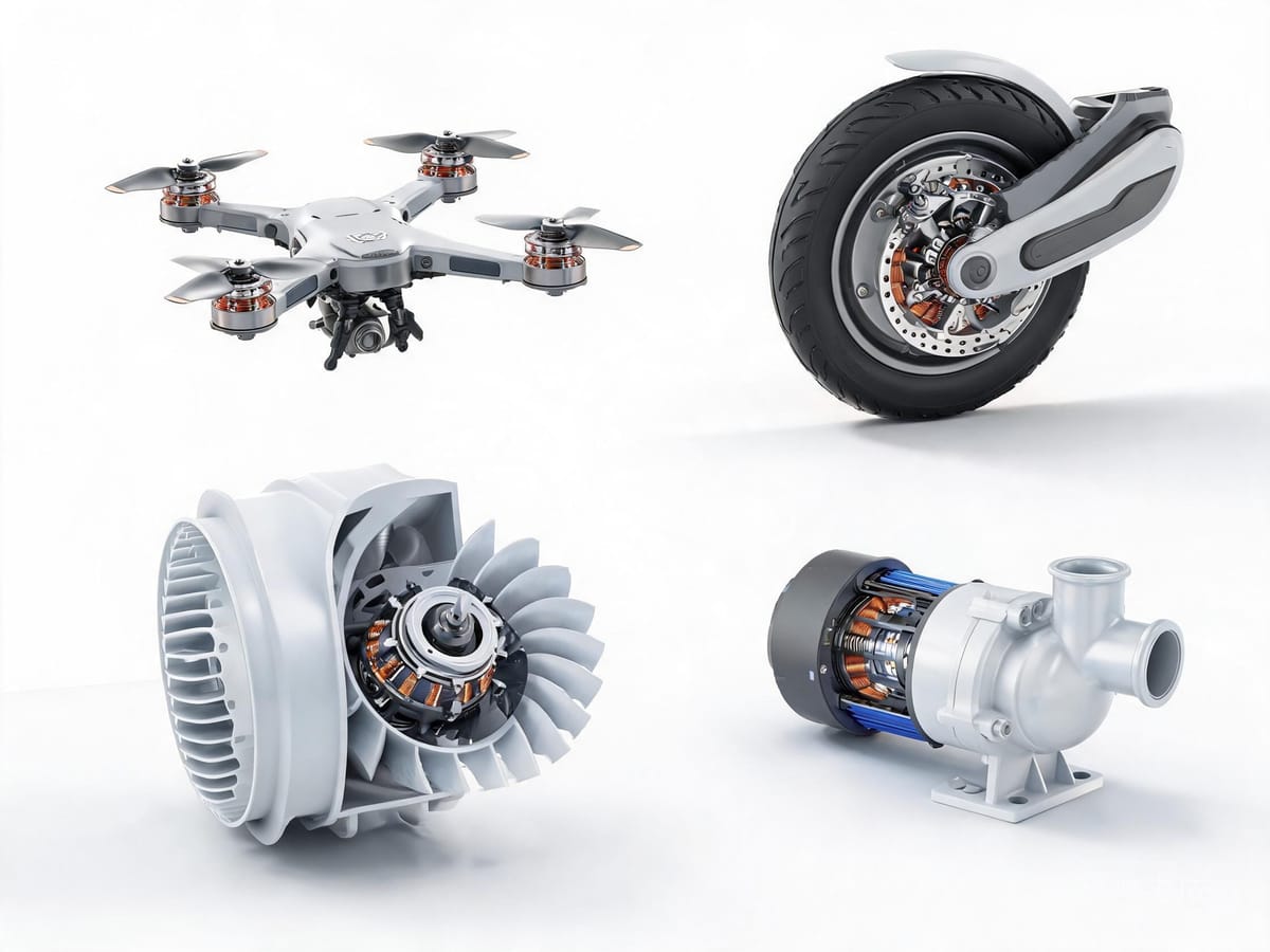
Figure: Typical BLDC applications — drones, EV hub motors, fans and pumps where power density and efficiency take priority
Five-Step Selection
Define the torque and speed curve — find the peak torque (usually in the starting or acceleration segment);
Define the supply voltage — low voltage (24/48V) is safer; high voltage (220/310V) gives better power density;
Define the sensor solution — needs load starting/low-speed high torque → Hall or encoder; otherwise sensorless;
Define the drive method — extremely cost-sensitive use six-step square wave; low-noise high-efficiency use FOC;
Define the structural form — separate (motor + driver) or integrated (drive-in-one).
The Reference Value of Integrated BLDC
Taking Limaisheng NiMotion's BLM42 series integrated brushless motor as an example:
Item | Parameter |
|---|---|
Supply voltage | DC 24V |
Rated power | 25 W / 45 W |
Rated speed | 3000 rpm |
Rated current | 1.1 A / 2.8 A |
Rated torque | 0.08 N·m / 0.15 N·m |
Drive method | FOC + SVPWM |
Encoder | Integrated 2500-line |
Communication | CANopen / RS485 |
Braking resistor | Built-in 16W + external supported |
Operating environment | 0–40°C, 10%–85% RH (non-condensing), altitude < 1000 m |
The value of the integrated form is that it integrates the BLDC controller, encoder, and communication interface entirely into the motor body. The user only needs to connect DC 24V power and one communication cable to directly control speed, position, and torque via CANopen or RS485, and read real-time status.