
Stepper Motor Working Principle Explained: Hybrid Structure, Step Angle, Microstepping and Torque-Frequency Characteristics
A stepper motor is a motor that directly converts electrical pulse signals into angular or linear displacement. All of its charm and all of its weaknesses stem from the same fact: it walks in "steps," not by running continuously.
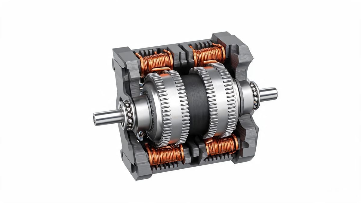
Figure: Hybrid stepper motor cutaway — rotor permanent magnet with toothed soft iron and stator windings at a glance
1. Basic Definition and Working Principle
Definition
A stepper motor (Stepper Motor / Step Motor) is an actuator that converts electrical pulse signals into angular or linear displacement. Each input pulse rotates the motor by a fixed angle — this angle is called the step angle.
Therefore it has a very attractive characteristic: without any position sensor, the total angle rotated = number of pulses × step angle. This is the physical basis of "open-loop positioning."
Working Principle: Let the Rotor Keep Chasing the Magnetic Field
The basic working principle of a stepper motor is: energize the stator phases in sequence to produce a rotating magnetic field, so that the rotor keeps aligning with the magnetic field, thereby achieving rotation.
The specific process is:
The stator has multiple phase windings (two-phase hybrid is most common: phase A, phase B);
The driver energizes each phase in a fixed sequence, and the stator produces a "stepping" rotating magnetic field;
The rotor is a permanent magnet or a toothed soft-magnetic body; to stay in the position of minimum reluctance (lowest energy), it follows the magnetic field;
Each time the driver switches the energization state, the magnetic field "jumps" one step, and the rotor follows one step.
Construction
After opening up a stepper motor, it mainly contains:
Part | Composition |
|---|---|
Rotor | Iron core, permanent magnet, shaft, ball bearings |
Stator | Windings (coils), stator iron core |
Structural parts | Front end cap, rear end cap, bearings |
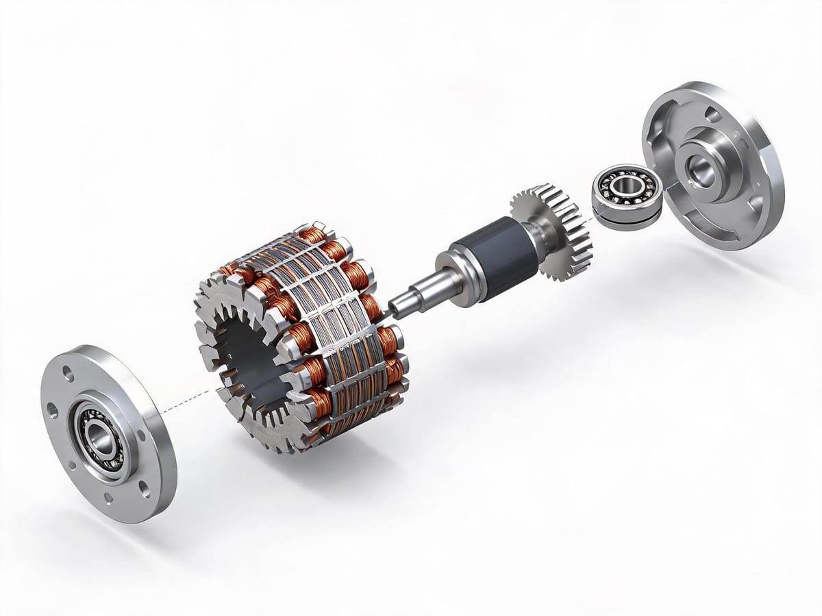
Figure: Stepper motor exploded view — assembly relationship of rotor, stator windings, front/rear end caps and bearings
2. Three Basic Types
By rotor structure, stepper motors are divided into three types:
Type | English | Rotor Structure | Step Angle | Features |
|---|---|---|---|---|
Permanent Magnet (PM) | Permanent Magnet | Permanent magnet steel, multiple poles | Larger, e.g., 7.5°, 15° | High torque, low cost, but coarse step angle and low accuracy |
Variable Reluctance (VR) | Variable Reluctance | Toothed soft-magnetic rotor, no permanent magnet | Can reach 1.5° or even smaller | Simple structure, small step angle, but low torque, no detent torque; rarely used now |
Hybrid (HB) | Hybrid | Permanent magnet + toothed soft iron composite | 1.8°, 0.9° are mainstream | Combines the advantages of PM and VR: small step angle, high torque, high accuracy |
Over 95% of industrial applications use two-phase hybrid stepper motors (Hybrid Stepper Motor), with a step angle of 1.8° (200 steps/rev) or 0.9° (400 steps/rev). This is also the core concept behind the English search term "what is hybrid stepper motor."
Where Does the Step Angle Come From?
The step angle of a hybrid stepper motor is determined by the number of rotor teeth and the number of phases:
Step angle θ = 360° / (number of phases × number of rotor teeth × step coefficient)
For a common two-phase hybrid motor with 50 teeth on the rotor, driven in two-phase four-step (full step):
θ = 360° / (2 × 50 × 2) = 360° / 200 = 1.8°
This means: 200 pulses are needed for one revolution. This is also why the default "pulses per revolution" of many stepper systems is 200 (full step), 400 (half step), and 3200 (1/16 microstep).
3. Drive Methods: Full Step, Half Step and Microstepping
Full Step
Switch only one phase at a time (single-phase energization) or energize two phases simultaneously (two-phase energization); the motor advances by a full step angle.
Single-phase energization (Wave Drive): low power consumption, but low torque;
Two-phase energization (Full Step): both phases excited simultaneously, torque about 40% higher than single-phase; the common industrial method.
Half Step
Alternate between single-phase and two-phase energization; the step angle is halved (1.8° → 0.9°), running more smoothly, but with slight torque fluctuation at low speed.
Microstepping — Standard on Modern Drivers
The core of microstepping is: instead of letting the winding current jump between "on" and "off," continuously adjust the two phase currents following sine/cosine laws, so that the resultant magnetic field rotates smoothly in space rather than jumping.
Common microstep settings: 1/2, 1/4, 1/8, 1/16, 1/32, 1/64, 1/256.
A misconception that must be clarified: microstepping improves resolution and smoothness, but does not proportionally improve accuracy.
There are three reasons:
The motor's own cogging effect and flux distortion cause deviation between actual and theoretical positions;
Friction and load mean that tiny current changes may not be able to push the rotor;
The driver's current control accuracy is limited; the finer the microstep, the smaller the current increment per microstep, and the larger the error proportion.
Engineering rule of thumb: the single-step accuracy after microstepping is usually only 5%–15% of full-step accuracy. So 1/16 microstep gives a theoretical resolution of 0.1125°, while the actual positioning accuracy is roughly on the order of ±0.02°–±0.1°.
Practical advice: don't be obsessed with high microstepping. On most equipment, 1/8 or 1/16 microstep + a well-tuned S-curve velocity profile gives better results (fewer lost steps, lower noise) than "1/256 microstep + trapezoidal velocity profile."
4. Core Characteristic: Why Does Torque Drop as Speed Increases?
This is the most important characteristic of a stepper motor and the number-one selection trap.
Physical Reason
When a stepper motor rotates, the inductance of each phase winding creates a back-EMF; the higher the frequency, the greater the back-EMF. Under its influence, as frequency increases the phase current decreases, thereby reducing torque.
A simple equivalent circuit helps: each phase winding is a resistor R in series with an inductor L. Building up the winding current i takes time, with time constant τ = L/R. When the pulse frequency rises and the on-time of each step approaches or becomes shorter than τ, the current has not yet reached the rated value before it is switched to the next step — insufficient current means insufficient torque.
Torque-Frequency Characteristic Curve
Plotting the "torque-speed" relationship gives the torque-frequency characteristic curve (Torque-Speed Curve / Pull-out Torque Curve). Its typical features are:
Low-speed segment: torque close to the holding torque, a plateau;
Medium-speed segment: torque drops rapidly as speed increases;
High-speed segment: torque decays to very low values; beyond a certain point the motor cannot start under load.
When sizing, look at two curves:
Pull-out torque curve: maximum load capacity during operation;
Pull-in torque curve: maximum load capacity for direct starting without acceleration/deceleration, significantly lower than the pull-out curve.
This means a stepper motor almost always needs an acceleration/deceleration profile — jumping directly from standstill to high speed will inevitably stall.
Three Engineering Countermeasures
① Raise the bus voltage (most effective)
High voltage can "push" current into the winding in a shorter time, directly countering the L/R time constant.
24V drive: torque typically decays severely around 1000 rpm;
48V–72V driving the same winding: often holds up to 1500–3000 rpm.
This is also why modern stepper drivers generally recommend 24–48V or even higher supply voltage.
② Choose a low-inductance winding
Within the same frame size, different winding specifications give vastly different inductance. Low-inductance (small resistance, small inductance) high-speed windings perform noticeably better in the high-speed range, at the cost of higher current and more heat at the same voltage. When selecting, you can ask the manufacturer for a "high-speed" winding version.
③ Set the driver current and idle-current reduction appropriately
Setting the running current lower than the rated value reduces heat but also reduces torque; the "idle current" (current during standstill holding) can be set lower than the running current to reduce temperature rise while ensuring no lost steps.
5. Overall Pros and Cons
Advantages
Advantage | Description |
|---|---|
Simple control | Pulse count = displacement, pulse frequency = speed, no PID tuning needed |
Open-loop positioning | No encoder needed, low system cost |
Stable accuracy | Per-step error does not accumulate (as long as no steps are lost) |
High torque at low speed | Higher torque density than a same-size servo at low speed |
Simple structure, maintenance-free | No brushes, no commutator, long life |
Power-off self-locking (some models) | Holding torque can keep the load in place |
Disadvantages
Disadvantage | Description | Mitigation |
|---|---|---|
Loses steps with no feedback | Overload/resonance causes lost steps, system unaware | Switch to closed-loop stepper |
Fast high-speed torque decay | Caused by winding inductance back-EMF | Raise bus voltage, choose low-inductance winding |
Vibration and noise | Discrete stepping + prone to resonance zones | Microstepping, S-curve profiling, avoid resonance speed range |
No overload capability | Must size by peak and leave margin | Leave 1.5–2× factor for worst-case conditions |
Higher heat | Still needs rated current when holding at standstill | Reduce idle current, switch to closed-loop solution |
6. Temperature: How Much Is Normal?
A frequent on-site question: the stepper motor housing is hot to the touch — is it broken?
The answer: most likely normal.
Excessive temperature can cause the motor's magnetic material to demagnetize, reducing torque;
The maximum allowable housing temperature depends on the magnetic material's demagnetization point, generally around 130°C;
Therefore a housing temperature of 80–90°C is completely normal.
A rough "hand test" criterion: if you can hold it for more than 3 seconds, it is usually below 70°C; if you pull your hand away instantly, it is generally above 80°C. For accurate judgment use a thermometer or thermocouple.
If the temperature is abnormally high, check in this order:
Is the running/holding current set too high;
Is it working for a long time in the low-speed high-current region (poor heat dissipation);
Is there mechanical jamming causing continuous stall;
Ambient temperature and heat dissipation conditions.
7. Open-Loop → Closed-Loop: The Evolution of the Stepper Motor
The biggest pain point of a traditional open-loop stepper is "lost steps without anyone knowing." The solution of the closed-loop stepper motor is very direct: add an encoder to the motor's rear, and the driver compares the commanded position with the feedback position in real time:
Deviation within the allowable range → normal operation;
Deviation exceeds the threshold → position-deviation alarm (instead of silently losing steps);
Some advanced algorithms increase current or send compensation pulses to correct the deviation when it appears.
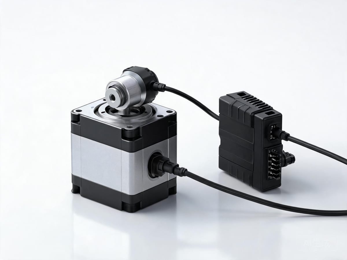
Figure: Closed-loop stepper motor — encoder added to the rear, the driver compares commanded and feedback positions in real time
The closed-loop stepper retains the cost advantage of the stepper while bringing three additional benefits:
No silent lost steps — equipment faults are perceivable;
Significantly lower heat — outputs current only when needed, no longer full current all the time;
Can tolerate some overload impact — transient overload does not immediately cause lost steps.
But it does not change the two physical weaknesses: torque-speed characteristics and overload capability. When sustained running above 2000 rpm or more than 2× overload is needed, you still need a servo motor.
Limaisheng NiMotion's STM series integrated stepper servo motors use this approach: the motor body integrates a 14-bit high-resolution absolute encoder, supports CANopen / RS485 communication, follows the CiA 402 protocol, and supports Profile Position mode (PP), Profile Velocity mode (PV), Velocity mode (VM), Interpolated Position mode (IP), Homing mode (HM), Cyclic Synchronous Position mode (CSP), and Cyclic Synchronous Velocity mode (CSV).