
How to Select an Integrated Stepper Motor: A Six-Step Method (2026 Guide)
Bottom line: Selecting an integrated stepper motor takes six steps — define the load and motion profile, calculate the required torque, choose the frame size, decide open-loop or closed-loop, pick the communication interface, then specify accessories and special machining. Below is each step in order, followed by a quick-reference table.
1. The six-step method at a glance
Table: Six-step selection method
Step | What to decide | Basis |
1 | Load type and motion profile | Horizontal or vertical load, stroke, max speed, accel/decel time |
2 | Required torque | Load torque + acceleration torque, times a safety factor |
3 | Frame size and body length | Torque headroom and mounting space: 28 / 42 / 57 / 86 mm |
4 | Open-loop or closed-loop | Whether step loss is acceptable; required accuracy and speed stability |
5 | Communication interface | Host system bus: CAN / CANopen / RS485 / RS232 |
6 | Accessories and machining | Brake, shaft extension, shaft key, lead screw, gear, timing pulley |
2. Step 1 — write down the load and motion profile
Most selection errors start here. Four things must be clear: whether the load is moved horizontally or lifted vertically (vertical axes need holding force and usually a brake), the stroke length, the maximum speed, and how much accel/decel time is available. Shorter accel/decel times mean higher acceleration torque and push the model up a size.
3. Step 2 — calculate torque with a safety factor
Required torque = load torque + acceleration torque. In practice, multiply by a safety factor of roughly 1.5–2 to get the reference torque for selection. One critical point: a stepper motor's torque falls as speed rises, so compare against the torque at the operating speed, not the static holding torque. This is the single most common beginner mistake.
Torque–speed curves for specific models are in the official Limaisheng product manual. Mark your operating point on the curve and confirm it sits below the curve with margin.
4. Step 3 — choose the frame size
Table: Frame size selection reference
Frame | Typical installation | Selection tip |
28 mm | Micro equipment, test instruments, small slides | First choice when space and load are both minimal |
42 mm | Compact automation equipment, multi-axis stations | The general-purpose workhorse with the best cost-performance |
57 mm | Medium loads needing higher torque | Richest model range; most derivatives live here |
86 mm | Larger loads and higher inertia | Choose when more torque is required |
Within one frame there are several motor lengths (34 / 40 / 41 / 48 / 56 mm); longer bodies deliver more torque. If the frame cannot change but torque is short, first check whether a longer body fits — jumping to a larger frame cascades into mounting holes and overall dimensions.
5. Step 4 — open-loop or closed-loop
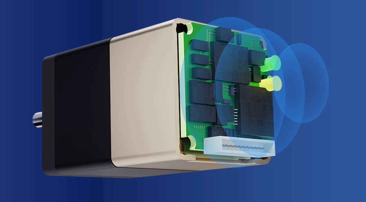
Open-loop (no "A" in the model code) is lower cost and simpler, and suits stable loads with no overload risk and no sensitivity to step loss. Closed-loop ("A", the STM-M integrated stepper servo series) adds closed-loop algorithms for better accuracy and speed stability, and is the right choice in three cases: the load fluctuates and overload is possible; higher positioning accuracy is needed; or low-speed operation must be vibration-free with no step loss.
6. Step 5 — choose the communication interface
Table: Communication interface comparison
Model code | Interface | When to use |
CANopen | CANopen bus | Multi-axis networks needing a standard motion-control protocol; widely supported by mainstream PLCs |
CAN | CAN bus | Host systems running a custom CAN protocol |
485 | RS485 | Serial networks with few axes and cable-cost sensitivity |
232 | RS232 | Point-to-point links, single-axis commissioning or built-in machine control |
PI | Pulse control signal | Retrofits reusing existing pulse-type controllers |
AI | Analog control | Applications where speed or position is commanded by an analog signal |
7. Step 6 — accessories and special machining
The model suffix lets you lock in accessories up front and avoid a second purchase: brake (B) — required for vertical axes and any position-holding-on-power-loss case; shaft extension 0 (standard) or 1 (non-standard); shaft key S (plain), F (milled flat), K (half-moon key), H (flat key), M (through-hole mounting); special machining A (gear), B (lead screw), C (peristaltic pump), G (timing pulley). For direct linear motion, choose a lead-screw model (STM28M / STM35M / STM42M / STM57M) and skip the coupling and extra structural parts.
8. Model code quick reference
Structure: STM - frame - length - operation - communication - feature - shaft extension - shaft key - special machining - brake. So STM 57 56 A - 485 - H - 0 F S B means: 57 mm frame, 56 mm body, closed-loop control, RS485, high-power control, standard shaft length, milled-flat shaft, no special machining, with brake.
9. Five common selection mistakes
Mistake 1 — using holding torque as working torque. Stepper torque drops with speed; always read the torque at the operating speed.
Mistake 2 — skipping the safety factor. Load variation, supply variation and temperature rise all eat margin; keep 1.5–2×.
Mistake 3 — no brake on a vertical axis. The load will fall when power is cut — a safety risk. Choose a "B" model for vertical axes.
Mistake 4 — selecting on torque alone. Changing frame size changes mounting holes, couplings and structural parts. Confirm space before locking the frame.
Mistake 5 — ignoring protocol matching. The communication code in the model must match the host bus, or you will need an extra converter.
10. FAQ
Q1: How do I tell open-loop from closed-loop quickly?Check for "A" in the model code — with A it is closed-loop (integrated stepper servo).
Q2: Torque is short — longer body or bigger frame?First check whether the same frame offers a longer body (34 / 40 / 41 / 48 / 56 mm); only step up a frame if that is not enough.
Q3: What about vertical mounting?Choose a brake-equipped model (suffix B) and verify the holding capability with power removed.
Q4: Which interface is best for a multi-axis network?CANopen is the more general choice with good PLC and motion-controller support; RS485 works when there are few axes and cost matters.
Q5: What if I need IP65 or a wide temperature range?Choose the STMP series (IP65) or STMPW57-M (wide temperature).