
How to Choose a 42/57/86 Stepper Motor: Complete NEMA Frame Size Guide and Torque Reference Table
The most important thing to say up front: a NEMA frame size only defines "how it mounts," not "how much force it can produce." A NEMA 17 motor's holding torque can range from 0.2 N·m to 0.6 N·m — a 3× difference. Selecting a motor by frame size alone is the most common stepper motor selection mistake.
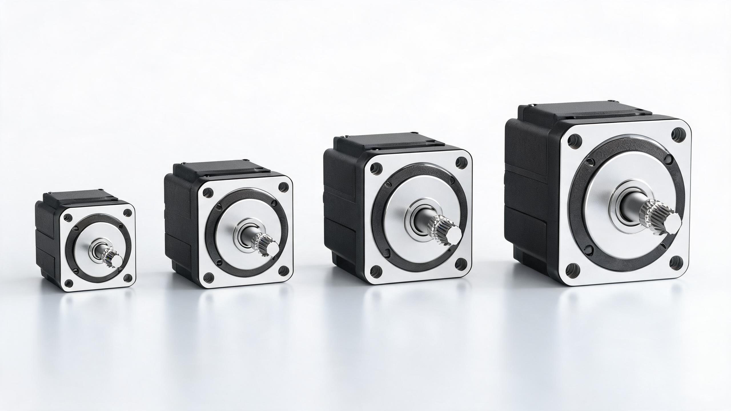
Figure: NEMA 8 / 17 / 23 / 34 stepper motors side by side — a frame size only defines mounting dimensions, not torque
1. What Is NEMA
NEMA = National Electrical Manufacturers Association.
For stepper motors, the relevant standard is NEMA ICS 16-2001 (Motion/Position Control Motors, Controls and Feedback Devices).
A NEMA Frame Size Only Defines These
The width and height of the square mounting flange (or the outer diameter of a round flange)
The diameter and position of the mounting holes
The diameter and depth of the locating pilot
The shaft diameter
A NEMA Frame Size Does Not Define These (all decided by the manufacturer)
Torque and speed
Rated current and voltage
Winding inductance and resistance
Step angle (1.8° / 0.9°)
Body length (axial length)
Special environmental conditions (temperature, protection rating)
Whether a gearbox or leadscrew is included
Connector shape and position
This explains why "two stepper motors that are both 42-frame can differ 2–3× in performance" — because their lengths and windings are completely different.
2. NEMA vs Metric Frame Size Comparison Table
NEMA Frame Size | Flange Size (inches) | Metric Frame Size | Actual Flange Size (mm) | Shaft Diameter (mm) |
|---|---|---|---|---|
NEMA 8 | 0.8" | 20 | 20 × 20 | 4 |
NEMA 11 | 1.1" | 28 | 28 × 28 | 5 |
NEMA 14 | 1.4" | 35 | 35 × 35 | 5 |
NEMA 16 | 1.6" | 39 | 39 × 39 | 5 |
NEMA 17 | 1.7" | 42 | 42.3 × 42.3 | 5 |
NEMA 23 | 2.3" | 57 | 57.2 × 57.2 | 6.35 (1/4") or 8 |
NEMA 34 | 3.4" | 86 | 86.3 × 86.3 | 9.525 (3/8") to 12.7 (1/2") or 14 |
NEMA 42 | 4.2" | 110 | 110 × 110 | 15.875 (5/8") or 19 |
Just remember this correspondence:
NEMA 17 = 42 frame, NEMA 23 = 57 frame, NEMA 34 = 86 frame
NEMA ICS 16-2001 Standard Dimensions (inches)
NEMA Size | Square Flange Width/Height (reference) | Round Flange Max OD BD | Pilot Diameter P | Pilot Depth T | Mounting Hole Diameter S | Shaft Diameter D |
|---|---|---|---|---|---|---|
17 | 1.7 | 2.36 | 0.8661 | 0.03–0.09 | 0.150±0.010 | 0.1969 |
23 | 2.3 | 3.21 | 1.5000 | 0.06–0.13 | 0.205±0.010 | 0.2500 |
34 | 3.4 | 3.58 | 2.8750 | 0.06–0.13 | 0.220±0.010 | 0.3750 |
42 | 4.2 | 6.19 | 2.1875 | 0.06–0.13 | 0.280±0.010 | 0.6250 |
Practical tip: The mounting hole center distance of a NEMA 23 is typically 47.14 mm (1.855"). Measuring this distance is the fastest way to identify a frame size in the field.
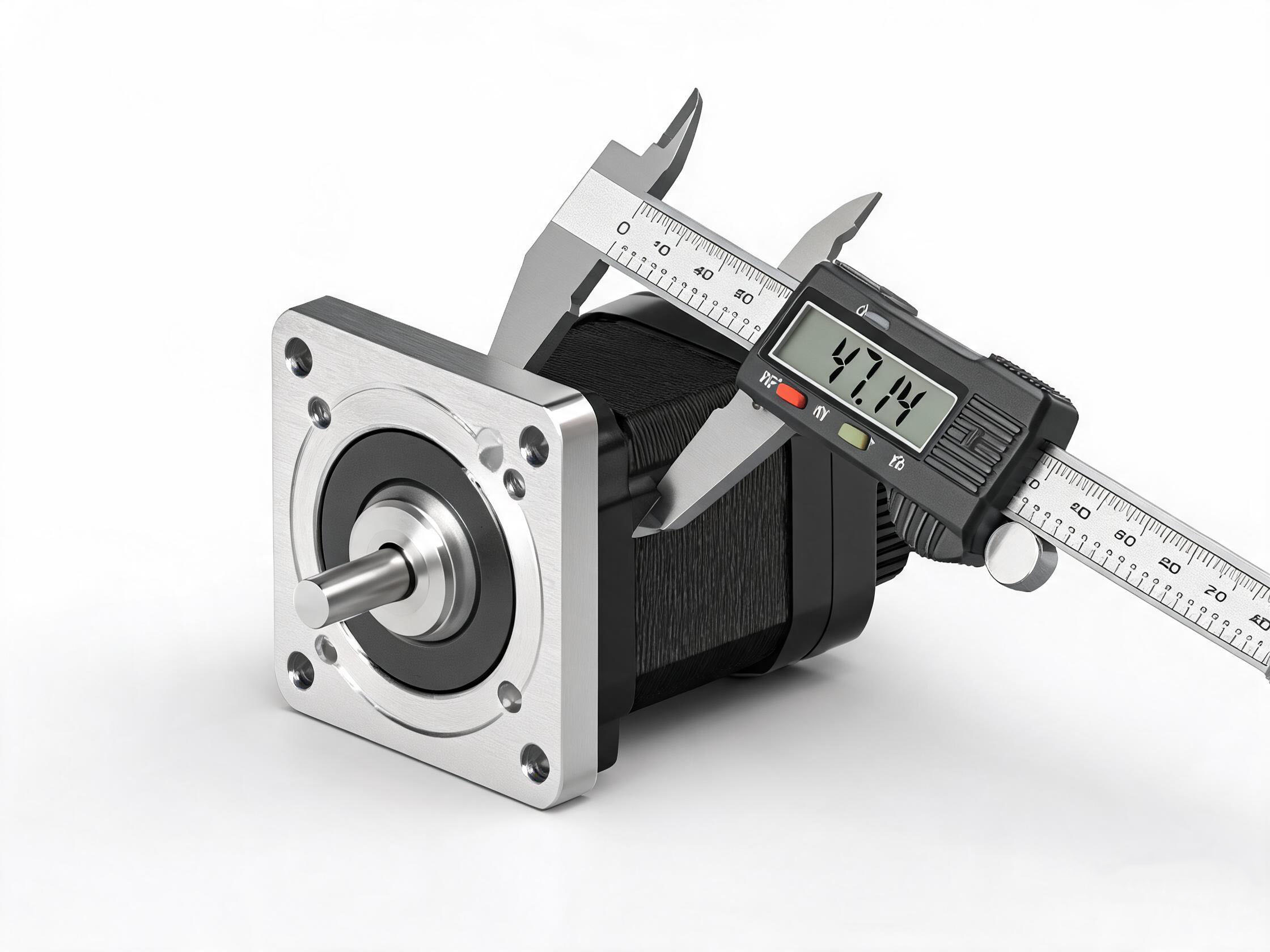
Figure: NEMA 23 square mounting flange — mounting holes, pilot and shaft diameter are the core dimensions a frame size defines
3. Typical Holding Torque Ranges
Within the same frame size, the longer the body, the higher the torque. The following are typical industry ranges (for quickly establishing order of magnitude; always refer to the manufacturer's data):
Frame Size | Flange Size | Typical Holding Torque Range | Typical Current | Common Applications |
|---|---|---|---|---|
NEMA 8 (20) | 20 × 20 mm | 0.02–0.05 N·m | 0.3–0.6 A/phase | Micro medical, optical fine adjustment |
NEMA 11 (28) | 28 × 28 mm | 0.05–0.15 N·m | 0.5–1.0 A/phase | Small pumps and valves, portable equipment |
NEMA 14 (35) | 35 × 35 mm | 0.1–0.3 N·m | 0.5–1.2 A/phase | Small automation, camera gimbals |
NEMA 17 (42) | 42 × 42 mm | 0.2–0.6 N·m | 1.5–2.0 A/phase | 3D printers, small CNC, pick & place |
NEMA 23 (57) | 57 × 57 mm | 0.5–3.0 N·m | 2.0–4.0 A/phase | Semi-professional CNC, laser cutting, automation |
NEMA 34 (86) | 86 × 86 mm | 3.0–12.0 N·m | 4.0–6.0 A/phase | Industrial CNC, presses, heavy machinery |
NEMA 42 (110) | 110 × 110 mm | 10–30 N·m | 5–8 A/phase | Heavy industry, large machine tools |
Key reminder: When comparing motors from different manufacturers, you must compare at the same body length. A 2–3× difference in holding torque between two NEMA 17 motors is completely normal.
Limaisheng NiMotion Reference Parameters
Series | Frame | Rated Current | Holding Torque | Protection Rating | Operating Temperature |
|---|---|---|---|---|---|
STM20/28/35 | 20/28/35 mm | 0–1.5 A adjustable | Micro | Model-dependent | 0–40°C |
STM42 | 42 mm | 0–1.5 A adjustable | 0.05 / 0.10 N·m (short body) | Model-dependent | 0–40°C |
STM57 | 57 mm | Model-dependent | Medium (< 3.0 N·m) | IP6K4 | -40 to +85°C |
STM86 | 86 mm | 3.0 / 4.2 A | 1.2 / 1.8 N·m | IP65 | -40 to +75°C |
4. The Correct Selection Workflow (Four Steps)
Step 1: Determine the Mechanical Interface
First check how much space the equipment can leave for the motor and what the flange hole pattern is. This step determines the upper limit of the frame size, but does not decide the final selection.
Step 2: Calculate the Required Torque (the Real Deciding Factor)
Trequired = Tfriction + Tacceleration + Tgravity + Texternal
Tacceleration = J × β (moment of inertia × angular acceleration), usually the largest term;
Leadscrew mechanism: T = (F × PB) / (2π × η);
Timing belt / rack and pinion: T = F × r.
Safety factor: use 1.5–2×. Stepper motors have no overload capability; for high-acceleration or vertical-axis applications, 2–4× is recommended.
Step 3: Check the Torque-Speed Curve and Verify Actual Torque at the Operating Speed
This step is the most often skipped and the most likely to cause problems.
A stepper motor's torque decays rapidly as speed increases. Selecting with the static holding torque is equivalent to assuming the motor always runs at zero speed.
The correct approach:
Determine the pulse frequency (pps) corresponding to the maximum operating speed;
Find the torque at that frequency on the torque-speed characteristic curve;
Use this torque (not the holding torque) for verification.
Rule of thumb: the pull-out torque should be ≥ 1.5× the required torque; if direct starting is needed (no acceleration/deceleration), also verify with the lower pull-in torque curve.
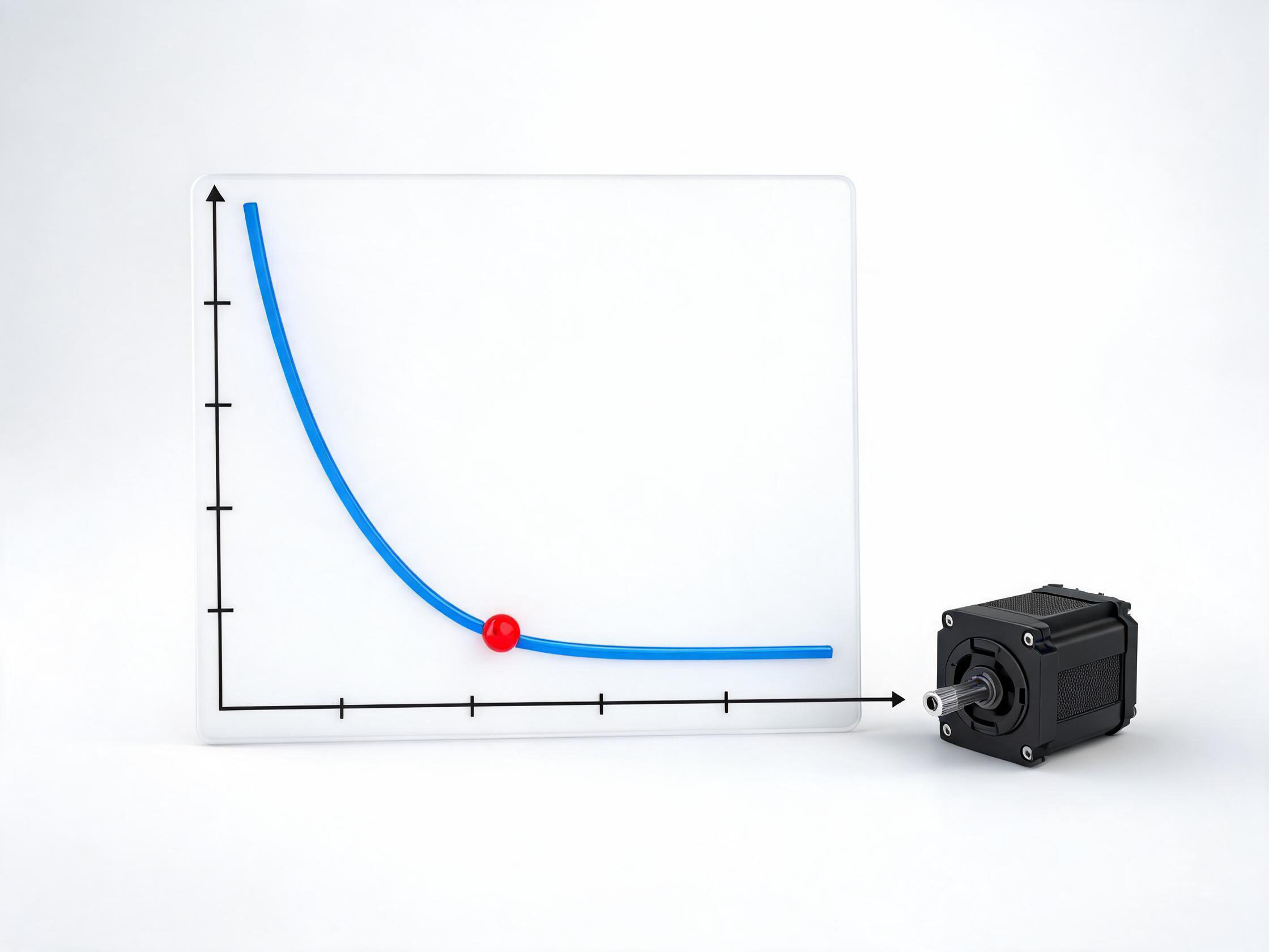
Figure: During selection you must verify the actual torque at the operating speed with the torque-speed curve, not the static holding torque
Step 4: Choose the Length and Winding
Within the same frame size:
Need more torque → choose a longer body (thicker lamination stack);
Need better high-speed performance → choose a low-inductance high-speed winding (higher current at the same voltage, and also higher heat);
Heat-sensitive → choose a closed-loop solution (outputs power on demand, reducing temperature rise by 30%–50%).
Practical rule: if the torque margin exceeds 100% of the actual requirement, you can step down one frame size. Systematically "sizing up one frame" adds weight, reduces efficiency, and does not improve accuracy.
5. Matching Voltage and Current
How to Set the Voltage
The higher the bus voltage, the better the high-speed performance — this is the most effective way to counter the winding's L/R time constant.
Supply Voltage | Typical Torque Collapse Speed |
|---|---|
24 V | About 600–1000 rpm |
48 V | About 1500–2000 rpm |
48–72 V | About 1500–3000 rpm |
Conclusion: as long as the equipment runs above 600 rpm and needs to carry a load, you should consider 48V instead of 24V.
How to Set the Current
Running current: set to the manufacturer's rated value; this is the source of torque;
Idle current (static holding current): can be set lower than the running current to reduce temperature rise while still preventing lost steps;
Drivers usually support 0–1.5 A (small sizes) or a wider adjustable range.
Common misconception: setting the running current far above the rated value "to get more force." The result is sharply increased heat, demagnetization of the magnetic material, and actually reduced torque. Magnetic materials generally demagnetize around 130°C; a motor housing temperature of 80–90°C is completely normal, but be alert if it exceeds that.
6. Typical Application Division of the 42 / 57 / 86 Frames
42 Frame (NEMA 17) — The Most Versatile
Features: small size, low cost, richest ecosystem.
Typical applications:
3D printers (extruder, X/Y axes)
Small CNC, laser engraving
Pick & Place mechanisms
Dispensers, small SMT
Camera gimbals, valve actuators
Medical equipment (syringe pumps, analyzers)
Application boundary: torque requirement < 0.6 N·m, speed < 1000 rpm.
57 Frame (NEMA 23) — The Industrial Workhorse
Features: the balance point between torque and size; the most widely used in industrial automation.
Typical applications:
Semi-professional CNC, laser cutting
Positioning and conveying in automated production lines
Packaging machinery, labeling machines
AGV drive and steering
Electric grippers, electric cylinders
Logistics sorting
Application boundary: torque requirement 0.5–3.0 N·m, speed < 800 rpm.
86 Frame (NEMA 34) — Heavy Duty
Features: high torque, suitable for heavy loads.
Typical applications:
Industrial CNC feed axes
Presses, stamping machines
Large conveyors and lifts
Heavy automation equipment
Application boundary: torque requirement 3.0–12.0 N·m.
Note: the 86 frame often enters the range where "a servo is more appropriate." If high speed or high dynamics are needed, seriously compare a servo solution.
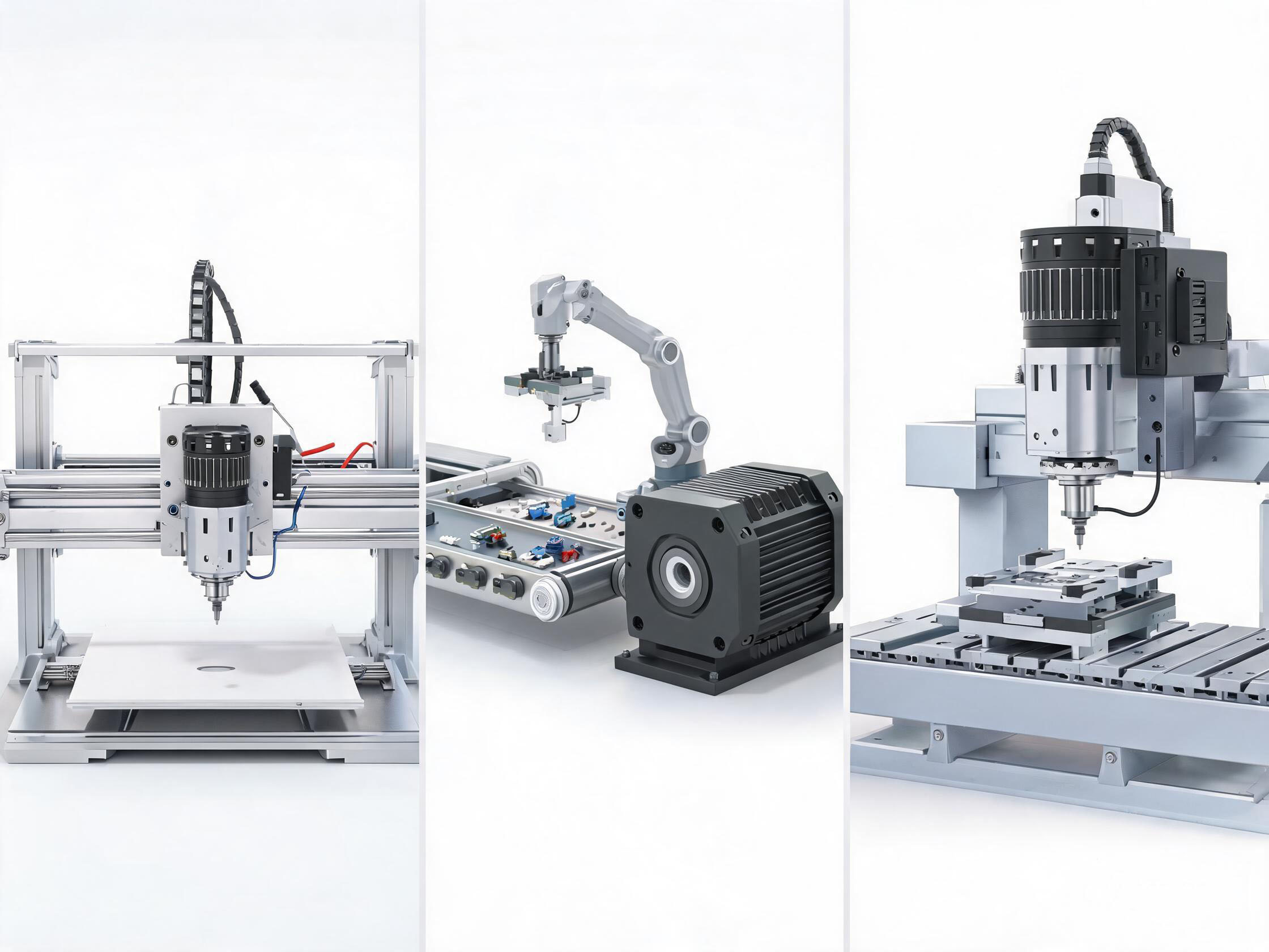
Figure: Typical application division — 42 frame (3D printers), 57 frame (automated production lines), 86 frame (industrial CNC)
7. How Integrated Motors Change the Selection
Traditional selection is "choose the motor first, then the driver, then wire it up." An integrated (drive-in-one) motor changes this workflow:
Traditional Solution | Integrated Solution |
|---|---|
Choose motor → choose driver → add encoder cable → run pulse wires | Choose an integrated motor (driver + encoder + communication already included) |
6–10 wires per axis | 2–3 wires per axis |
Needs pulse output points | Bus networked, no point-count limit |
Open-loop, no feedback | Built-in encoder, lost steps can alarm |
Impact on 42/57/86 selection:
The frame size selection logic is unchanged (still based on torque and flange size);
But you no longer need to select a separate driver, nor consider the number of pulse ports;
You can directly choose a closed-loop type for lost-step protection, at a cost increment far smaller than a traditional "open-loop + external closed-loop driver" solution.
For example: Limaisheng NiMotion's STM57/STM86 integrated stepper servo motors integrate the driver and an absolute encoder within the 57/86 frame. Externally there are only two wires — DC power + CANopen/RS485 — with protection ratings of IP6K4 and IP65 respectively, and operating temperatures covering -40 to +85°C / -40 to +75°C.