
Servo Motor vs Stepper Motor: 7-Dimension Deep Comparison and Selection Guide
Bottom line: A stepper motor is a "open-loop, low-cost, high-torque-at-low-speed" position actuator; a servo motor is a "closed-loop, high-dynamic, high-speed and high-precision" motion control actuator. The real dividing line is not "which is more accurate," but whether your load will exceed the motor's capability boundary during operation — if it does, a stepper will lose steps without anyone knowing, while a servo will alarm and self-correct.
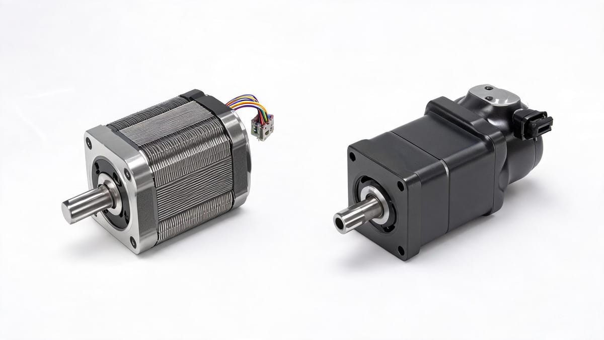
Figure: Servo motor (right) vs stepper motor (left) — comparison of appearance, structure and mounting
Why This Question Deserves a Serious Answer
In automation equipment motor selection, "stepper or servo" is almost the first choice every mechanical engineer faces. The cost of choosing wrong is very real:
Choose too big: BOM cost, size, and cabling cost all rise, and the equipment loses price competitiveness;
Choose too small: lost steps, abnormal noise, and positioning drift appear during mass production, and after-sales costs far exceed the money saved on the motor.
This article does not pile up parameters. Instead, it compares 7 dimensions that truly affect the decision and ends with a decision table you can follow directly.
1. First Look at the Essence: Different Control Methods Determine All Subsequent Differences
Stepper Motor: An Open-Loop System That Counts Pulses
A stepper motor is an actuator that converts electrical pulse signals into angular displacement. Each time the driver receives a pulse, the motor rotates by a fixed step angle. A common two-phase hybrid stepper motor has a step angle of 1.8°, i.e., 200 pulses per revolution (360° ÷ 1.8° = 200).
The key point: the system assumes the motor actually rotated that much. The driver only sends pulses and does not check whether the rotor kept up. This is "open-loop."
Once the load changes suddenly, acceleration is too high, or the motor dwells in a resonance zone, the rotor cannot keep up with the magnetic field and "loses steps" — and the controller has no idea. This is the core risk of the stepper approach.
Servo Motor: Three-Loop Closed Loop, Correcting at All Times
A servo motor is not "a motor" but a closed-loop system consisting of motor + driver + encoder. The encoder at the motor's rear continuously feeds back position, and the driver compares the command value with the feedback value and immediately corrects the current output.
Inside the servo driver is a three-layer nested closed loop (cascade PID), from inner to outer:
Loop | Controlled Object | Feedback Source | Typical Response Period | Function |
|---|---|---|---|---|
Current loop (innermost) | Winding current = output torque | Driver-internal Hall/sampling resistors | 50–100 μs | Determines "how hard to push," also provides overcurrent protection |
Speed loop (middle) | Motor speed | Encoder position differentiation | 200–500 μs | Determines "how fast to run," suppresses oscillation and overshoot |
Position loop (outermost) | Final positioning | Encoder position | 500 μs–1 ms | Determines "where to go," guarantees steady-state accuracy |
Engineering experience: The inner loop bandwidth must be significantly higher than the outer loop, typically current loop > 5× speed loop > 5× position loop. If this hierarchy is violated, the system will oscillate.
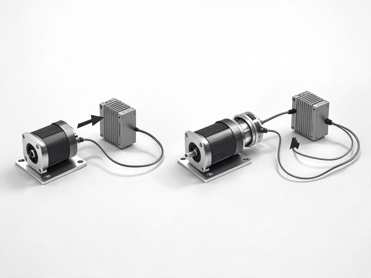
Figure: The control logic difference between stepper "open-loop pulse counting" and servo "three-loop closed-loop correction"
2. Deep Comparison Across 7 Dimensions
Dimension 1: Control Method and Lost-Step Risk
Stepper Motor | Servo Motor | |
|---|---|---|
Feedback | None (open-loop) | Encoder (closed-loop) |
Overload/stall | Loses steps directly, system unaware | Reports overload/stall alarm and stops |
Recovery | Usually needs homing again | Continues after fault is cleared |
This is the most fundamental difference. For any application that "cannot make mistakes" (medical equipment, semiconductors, long-term unattended production lines), servo is almost the only choice.
Compromise: closed-loop stepper motor. Add an encoder to the rear of the stepper; the driver alarms or sends compensation pulses when the position deviation exceeds a threshold. It retains the stepper's cost advantage and solves the "lost steps without anyone knowing" problem, but low-speed smoothness and high-speed torque still fall short of servo.
Dimension 2: Torque-Speed Characteristics (Easiest to Overlook)
The biggest physical weakness of a stepper motor: torque decays rapidly as speed increases.
The reason is direct — as the motor rotates, the inductance of each phase winding generates back-EMF. The higher the frequency, the greater the back-EMF, which reduces the phase current and thus the torque. In practice, a 24V stepper motor may drop to one-third of its holding torque after 600 rpm.
A servo motor provides constant torque within rated speed and only enters the constant-power field-weakening region above rated speed. Therefore:
Low speed (< 600 rpm), light-to-medium load → stepper offers excellent cost-effectiveness;
High speed + torque still needed at high speed → servo is required.
A practical tip to improve stepper high-speed performance: raise the bus voltage. A 24V-driven stepper visibly loses torque around 1000 rpm; the same winding driven at 48V often holds up to 1500–3000 rpm before collapsing, because higher voltage overcomes the winding's L/R time constant faster.
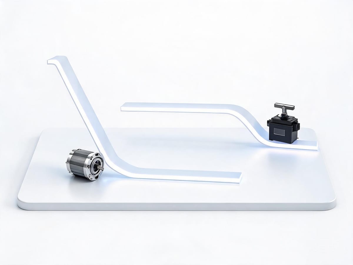
Figure: Stepper torque decays rapidly with speed; servo maintains constant torque within rated speed
Dimension 3: Overload Capability
A servo motor generally has 2–3× rated torque short-time overload capability (some up to 3× or more), used to overcome starting inertia, mechanical shock, and instantaneous cutting forces.
A stepper motor has no overload capability. During selection you must match the motor to the peak torque of the worst-case condition and leave a 1.5–2× safety factor — this is also why steppers "look adequate on paper but run hot in practice."
Dimension 4: Accuracy and Resolution
Stepper Motor | Servo Motor | |
|---|---|---|
Resolution source | Step angle × microstepping | Encoder resolution |
Typical value | 1.8°/step, 1/16 microstep → 0.1125° | 17-bit → 131072 positions/rev; 20-bit+ is common |
Nature of accuracy | Theoretical open-loop resolution; errors accumulate after lost steps | Actual closed-loop guaranteed accuracy |
Note a common misconception: microstepping improves resolution and smoothness, not accuracy. The accuracy of microstepped positions is affected by current control accuracy, friction, and cogging effects, typically only 5%–15% of a full step.
Dimension 5: Low-Speed Smoothness, Vibration and Noise
A stepper motor operates in discrete step angles, so it naturally has stepping sensation, low-frequency vibration, and noise. Especially in the 100–200 rpm range it can fall into mechanical resonance, producing obvious abnormal noise or even stalling.
A servo motor, due to continuous closed-loop control, is extremely smooth at low speed, and with a notch filter it can also actively suppress mechanical resonance.
If the equipment is noise-sensitive (medical instruments, laboratory analysis equipment, office-environment equipment), this criterion is often decisive.
Dimension 6: System Cost and Integration Complexity
This is the stepper's home turf. A traditional servo system requires: servo motor + servo driver + encoder cable + power cable + control cabinet space + in-cabinet wiring and heat dissipation design.
A stepper solution usually needs only: motor + a small driver, or even further, an integrated (drive-in-one) motor — the driver is integrated directly into the motor's rear end cap, leaving only a power cable and a communication cable.
Taking Limaisheng NiMotion integrated stepper/servo motors as an example: the motor body integrates a 14-bit absolute encoder (stepper series) or a 2500-line encoder (servo series), and CANopen / RS485 / EtherCAT connect directly to the bus, eliminating the driver, encoder cable, and 80% of in-cabinet wiring. For multi-axis equipment (AGVs, collaborative robots, multi-station inspection equipment), this saving is an order of magnitude.
Dimension 7: Inertia Matching and Dynamic Response
Servo selection always requires calculating the load inertia ratio:
Load inertia ratio = load inertia reflected to the motor shaft ÷ motor rotor inertia
The industry rule of thumb is to keep it within 5:1, ideally close to 1:1. If the ratio is too large, the system responds slowly and tends to oscillate, and tuning difficulty rises sharply.
Steppers generally do not strictly calculate the inertia ratio, but moment of inertia still determines the torque required for acceleration/deceleration:
M = I × β (torque = moment of inertia × angular acceleration)
So whether stepper or servo, whenever frequent start/stop is involved, you must first calculate the load inertia and acceleration torque. Skipping this step in selection usually means rework.
3. Quick Comparison Summary Table
Comparison Dimension | Stepper Motor | Servo Motor |
|---|---|---|
Control method | Open-loop, pulse counting | Closed-loop, three-loop PID |
Lost step/overload | Loses steps with no feedback | Alarms and corrects |
Torque characteristics | Decays rapidly with speed | Constant torque within rated speed |
Overload capability | None | 2–3× short-time overload |
Max practical speed | Usually < 1000 rpm | Common 3000 rpm, can be higher |
Low-speed smoothness | Stepping sensation, prone to resonance | Extremely smooth |
Resolution | Step angle × microstepping | 17–23 bit encoder |
System cost | Low | High (about 2–4× the stepper) |
Tuning difficulty | Low, basically no tuning | Needs gain tuning (most auto-tune) |
Typical applications | 3D printers, dispensers, small conveyors, valves | CNC, robot joints, flying shear, precision positioning stages |
4. Selection Decision Tree: Follow It and You're Done
Step 1: Is the load torque stable and predictable?
No (impact, cutting, large friction variation) → go directly to servo.
Yes → continue to Step 2.
Step 2: Does the max running speed exceed 800–1000 rpm, and is significant torque still needed at that speed?
Yes → servo.
No → continue to Step 3.
Step 3: Can you accept batch scrap or downtime caused by lost steps?
No → closed-loop stepper or servo.
Yes → continue to Step 4.
Step 4: Is the number of axes ≥ 4, or are installation space/wiring costs sensitive?
Yes → integrated stepper motor (drive-in-one, bus networked).
No → open-loop stepper motor is sufficient.
Application Condition Reference Table
Typical Equipment | Recommended Solution | Reason |
|---|---|---|
3D printer, desktop CNC | Open-loop stepper (NEMA 17 / 42 frame) | Low speed, light load, extremely cost-sensitive |
Dispenser, small SMT | Open-loop or closed-loop stepper | Medium-low speed positioning, stable load |
Medical analyzer, syringe pump | Closed-loop stepper / integrated stepper | Lost steps not allowed, low noise required |
AGV / AMR drive and steering | Integrated servo (low-voltage 24/48V) | Battery powered, compact, needs overload capability |
Collaborative robot joints | Integrated servo + absolute encoder | High dynamic, needs position retention on power loss |
Packaging flying shear / rotary cut | Servo (EtherCAT) | Multi-axis synchronization, microsecond sync accuracy |
Electric gripper, electric cylinder | Integrated servo/stepper | Integration priority, short stroke |
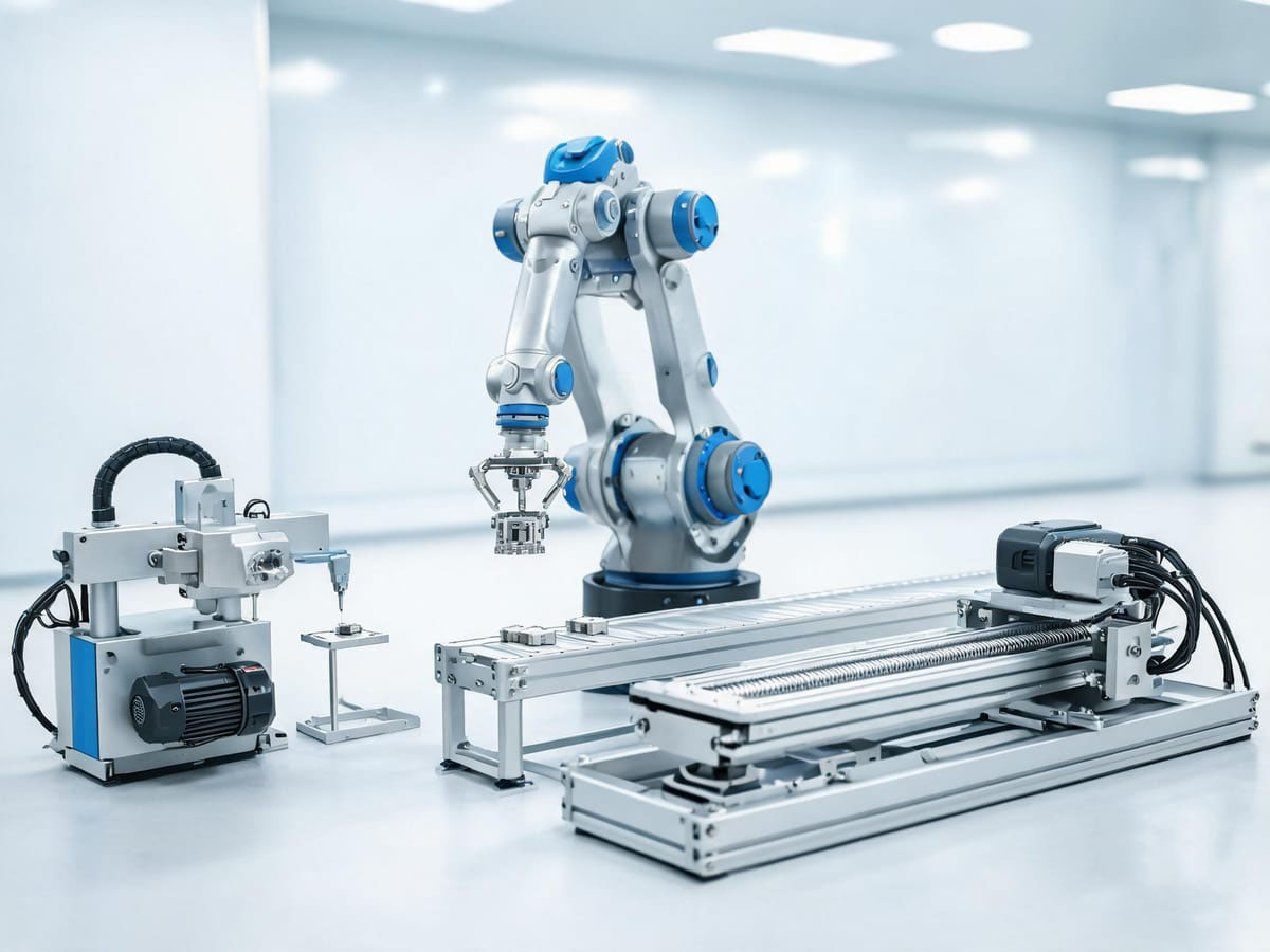
Figure: Motor applications in precision positioning and automated production lines
Summary
Choosing between stepper and servo is essentially answering three questions: Will the load exceed expectations? Is the speed high? Is the cost of error high?
All three answers are "mild" → stepper, spend the money saved on mechanical precision;
Any answer is "severe" → servo;
Stuck in the middle → closed-loop stepper, or directly consider an integrated bus motor, trading integration for cost.
Limaisheng NiMotion offers a full range of integrated stepper, servo, and brushless motors from 20mm to 86mm frames, supporting CANopen, RS485, EtherCAT, Modbus, and Profinet buses. We can provide selection calculations and prototype testing support based on your load curve and operating conditions.