
Motor Runs but Speed Is Wrong: One Parameter to Fix It

The welding torch of an automatic welding device advances at a steady pace along the screw drive — speed is its lifeline
The customer said one sentence on the phone that stuck with us.
"The motor is turning, but the speed is wrong."
The feedback came from Ultrasonic. Their automatic welding device carries one of our STM2851B-CANopen-M-0FS motors: the host sends commands, and the motor drives the torch along its path. The equipment raised no alarms, dropped no connections, and moved smoothly — yet the speed simply did not match the setpoint.
In welding, a small error in speed means a whole weld seam goes wrong.
1
Abstract · Background
Ultrasonic builds ultrasonic technology equipment; what went live here was an automatic welding device, using 1 motor per unit.
The mechanical arrangement is a classic combination: a motor plus a gearbox, driving a ball screw through a coupling, converting the motor's rotation into the torch's linear motion. The host handles overall control, while the motor side operates in HM mode (homing mode) and PP mode (position mode). On every power-up it first homes to establish the reference point, then follows the programmed path to weld.
During integration, the motor's speed came out off. We picked up the problem in a remote support session.
2
Device Overview · Automatic Welding Equipment
Automatic welding equipment translates a welder's craft into machine motion. A person holds the torch, watching the weld pool with their eyes and controlling speed by feel; a machine holds the torch, walking a path with a motor and setting parameters with a program.
Its motion unit follows a well-worn recipe. The servo motor produces torque, the gearbox multiplies it and cuts speed, the coupling passes the power to a ball screw, and the screw drives the torch in a straight feed. In published dedicated-welding-machine designs, this structure appears constantly — paired with a multi-axis motion control platform, the torch can trace complex weld seams.
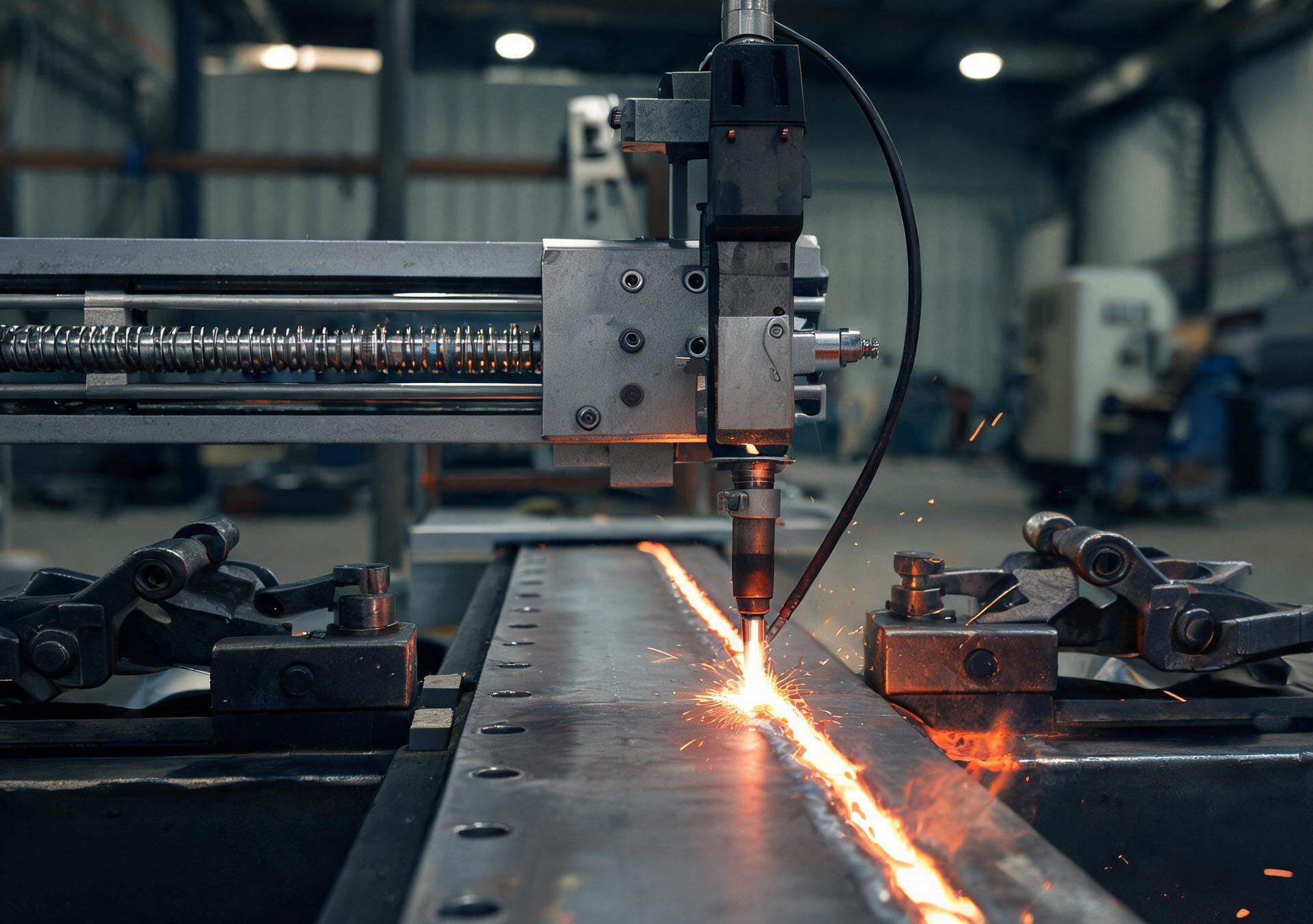
The motion platform of a dedicated welding machine: the motor connects directly to the ball screw through a coupling, driving the torch along a straight path
A cousin in the family is ultrasonic welding. Instead of an electric arc, it uses high-frequency mechanical vibration between 20 kHz and 40 kHz, generating frictional heat at the contact surface to fuse the materials together. The whole process completes in milliseconds, needs no glue or solder, and is a regular in the automotive, medical, electronics and packaging industries.
Different routes, identical demands on motion control: the feed must be steady and the speed exact. Welding speed directly determines heat input, and heat input determines weld quality. A 10% speed deviation can shift the entire bead profile and strength.
So when the customer reported "the speed is wrong," we knew this was no minor nuisance.
3
Application Solution
Nothing about the solution required special customization — it follows our mature workflow with dedicated-welding-machine customers like this one.
The motor is an STM2851B-CANopen-M-0FS speaking CANopen, with the host exchanging process data over the bus. Mechanically, the motor shaft reaches the ball screw through the gearbox and coupling, turning rotation into linear feed.
Control runs in two stages. On power-up the motor enters HM homing mode, hitting a limit switch or finding the home signal to establish the zero point of the mechanical coordinate system. Once homing completes, it switches to PP position mode, and the host sends target positions according to the weld seam plan, walking the motor through the path segment by segment.
Speed in this chain is not a quantity of its own. The host issues position commands; the actual speed is jointly determined by the cadence at which those commands are sent, the electronic gear ratio, and the conversion factors inside the motor. If any link's parameters fail to match the real hardware, the final rotational speed will drift.
4
Products Used
Product Model | STM2851B-CANopen-M-0FS |
Customer | Ultrasonic |
Application | Automatic welding device |
Mechanical Structure | Motor + gearbox, driving the screw through a coupling |
Operating Mode | HM homing mode, PP position mode |
Quantity per Unit | 1 |
5
Problems, Challenges & Solutions
The symptom was deceptively clean: the motor's speed did not match what the host commanded — sometimes fast, sometimes slow — yet the system raised no fault of any kind.
No alarm is actually the trickiest case. It means communication is up, the bus is healthy, and the motor is executing commands normally. The deviation was hiding in the mapping between parameters and hardware.
We first verified the mechanical and electrical side: the gear ratio checked out, the screw lead was correct, and target positions in PP mode completed normally. The problem was not in any of the visible places.
Next we examined the conversion parameters in the speed chain. In the CANopen object dictionary, 0x608F is the Gear factor — it determines how speed and position commands are scaled into encoder counts. We read the current value from the customer's motor.
Root cause. This motor's encoder had been upgraded, and the Gear factor was never updated to match.
Sub-index 01 of 0x608F currently read 131072, while for the customer's mechanics and host conversion, the correct value should have been 10000. Once the speed command passed through that wrong factor, the motor's actual speed was off across the board.
Problems of this kind share a common shape. After an equipment retrofit or a spare-parts swap, the hardware changes but the parameters don't — the two fall out of alignment, and the speed drifts. Debugging the motor and the wiring usually turns up nothing, because the fault lives in a single number in the dictionary.
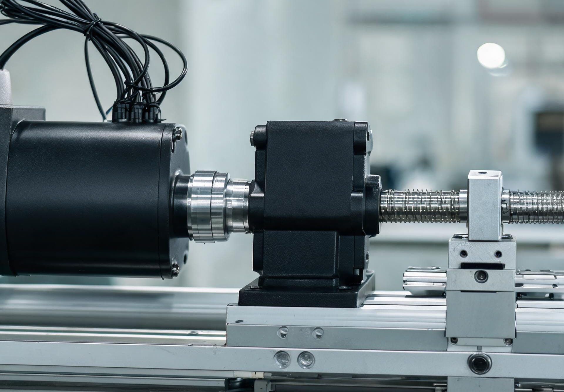
Motor and gearbox driving the screw through a coupling — only when parameters match hardware does the torch feed stay steady
Fix. In the debugging software, change sub-index 01 of 0x608F from 131072 back to 10000, write it, power-cycle, and re-home.
The motor's speed returned to normal and matched the host's setpoint. HM homing and PP path following passed end to end in integration, and the customer moved on to full-machine welding validation.
One remote support session, one parameter changed.
6
Conclusion
Two points in this case are worth remembering.
First, when a motor "runs wrong but raises no alarm," check the parameter-to-hardware match first. The encoder, the gearbox ratio, the screw lead — every physical quantity has a corresponding coefficient in the object dictionary. If the hardware has been touched, re-verify the coefficients.
Second, conversion parameters like 0x608F are stealthy. They don't announce themselves the way a miswired connection does, and they don't throw an exception the way a firmware fault does — they simply miscalculate the speed, quietly. There is no shortcut for catching them: read them one by one and check them one by one.
A day for welding equipment starts with homing. The motor finds its origin, the torch lays down the first bead, and the speed is exact to the digit.
Align the parameters with the hardware, and this machine can keep welding just like that.