
Fixing Capping-Station Positioning With One Parameter
On the production line of someone, the capping head travels only a few dozen millimeters per stroke. The customer wanted it to move decisively and stop precisely.
The field engineers told us the motion looks simple, but in fact it repeats tens of thousands of times a day. A slight positioning error and the cap goes on crooked — or gets scratched.
This was a typical issue from one of our on-site support visits, with a PMM6040B-485-0HEB at the center of it.
Abstract · Background
It runs a capping step on its production line: the equipment must press each cap down and screw it into place with precision. Each machine is fitted with 1 motor.
The customer's original control approach was to add an external pulse-control board. The board would emit pulses, driving the motor — and with it the capping head — up and down.
A conventional approach on paper. But once it was actually wired up, positioning was off and the stroke never matched what the mechanics required. No amount of on-site tuning sorted it out.
After receiving the feedback, we went on site and traced the problem from the motor parameters all the way to the board's pulse timing — until it narrowed down to a single setting.
The motor itself was fine. The pulse equivalence was misaligned.
Equipment Overview · Automatic Capping Machine
An automatic capping machine — known in the trade as a screw capper or crimping capper — is standard equipment on a filling line. Once bottles are filled on the conveyor, they must be sealed right away; the capper presses the cap onto the bottle neck, then screws it to the specified tightness.
Too loose and it leaks in transit; too tight and the end user can't open it — or worse, the bottle neck cracks. So this station has exactly one core metric: torque consistency.
In design, cappers fall into two common types: straight-down and rotary. A straight-down capper presses the capping head vertically, aligns it with the bottle neck, screws the cap on, then lifts. The motion is simple and changeover is fast, making it a good fit for high-mix, low-volume production. A rotary capper uses a star wheel to distribute bottles to the individual stations, where several capping heads screw caps on as the turret turns. High throughput — common on large-volume beverage and spirits lines.
Whichever structure is used, the capping head performs the same fixed sequence: descend, rotate, retract. The descent and retract strokes demand high repeatability — otherwise the starting position varies from bottle to bottle, and the torque drifts along with it.

Capping station on a filling line: the capping head must repeat the descend-and-retract motion over and over
This is where the motor comes in. The capping head is raised and lowered by the motor; how far it travels and where it stops are determined by the commands the control system sends to it.
With pulse control, every pulse sent moves the motor one step. How many pulses are sent determines how far it travels — and that only works if both sides are in agreement.
The Solution
The customer's setup: an external pulse-control board feeds pulse signals into the motor through its IO port. The motor moves to a fixed position based on the number of pulses it receives, driving the capping head up and down.
For control, we set the motor to pulse control mode and configured the electronic gear ratio at 10000 pulses per motor revolution.
This step set the conversion baseline for the whole machine. When the board sends 10000 pulses, the motor turns exactly one revolution — and both sides finally agreed.
From there it was straightforward: the mechanical side works out how many motor revolutions correspond to one capping-head stroke, multiplies by 10000, and that is the number of pulses the board must send. Send 5000 and the motor turns half a revolution; send 2000 and it turns one fifth. Every distance traveled, every stop, is a fixed and known number.
Control mode | Pulse control (external board, IO input) |
Pulse equivalence | 10000 pulses / revolution |
Action | Move up and down by a fixed pulse count |
Units per machine | 1 |
The motor receives the pulse signal directly through the IO port, with no intermediate conversion stages in between. The signal path is short, which also makes it more resistant to interference.
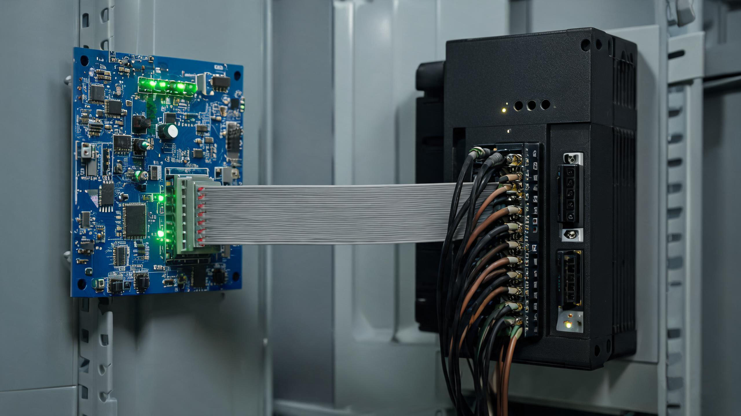
Under pulse control, every pulse from the board moves the motor a fixed distance per the equivalence ratio
Product Used
Customer | (A company of Guangdong) |
Model | PMM6040B-485-0HEB |
Application | Bottle-cap tightening station |
Units per machine | 1 |
Function used | Pulse control mode |
Problems, Challenges & Solutions
Symptom. Once the board was connected, the motor ran — but the travel never matched what the mechanics required. Sometimes it overshot and the capping head hit the limit stop; sometimes it fell short and the cap was not fully seated. The customer configured the parameters according to their own understanding, yet however they changed them, the result was off by a fixed ratio.
Troubleshooting. We ruled out the hardware first. The motor ran freely, the encoder feedback was correct, and the power supply and wiring were fine. We then turned to the board: measuring the pulse signal with an oscilloscope showed both the frequency and the pulse count being emitted — not a single pulse missing.
Both sides checked out as “normal,” so the problem could only lie in the conversion.
Root cause. When the board sends pulses, it works from its own figure for “how many pulses make one revolution.” The motor, once it receives those pulses, applies its own conversion. Because the two figures disagreed, command and execution were forever off by a fixed multiplier — and the stroke could never land on target.
Fix. We set the motor to pulse control mode, explicitly configured 10000 pulses per revolution, and had the board emit pulses according to that equivalence. Every pulse entering the IO port now corresponds directly to a fixed position for the motor.
Once both sides used the same conversion, the capping head landed on target in the very first test run. Across hundreds of bottles in a row, the descent position was identical every time.
In pulse-control commissioning, four out of five problems are not in the motor — they are in whether both sides agree on how many pulses equal one revolution.
Summary
This on-site visit replaced no hardware at all. Only two settings changed: control mode set to pulse, and pulse equivalence set to 10000 pulses per revolution.
With the right parameters, the stroke became accurate and the capping station returned to its normal rhythm.
Our advice to fellow machine builders: before wiring up pulse control, align three numbers first — the board's pulses per revolution, the motor's electronic gear ratio, and the mechanical stroke conversion. Work all three out on a single sheet of paper, and you will save most of your on-site commissioning time.
In a machine that repeats one motion tens of thousands of times a day, reliability never comes from piling on better components — it comes from every parameter agreeing with the next.
The value of technical support lies in helping the customer align the numbers on the exact parameter where they are stuck.