Servo Motor Sizing Step-by-Step: Complete Calculation Method from Load Torque to Inertia Matching (with Examples)
The essence of servo sizing is a calculation problem, not a choice problem. Sizing that skips the calculations and relies on experience "good enough" will expose problems in 90% of cases during commissioning: either slow response, oscillation, or overload alarms the moment you accelerate. This article provides a 7-step process you can follow and calculate directly.

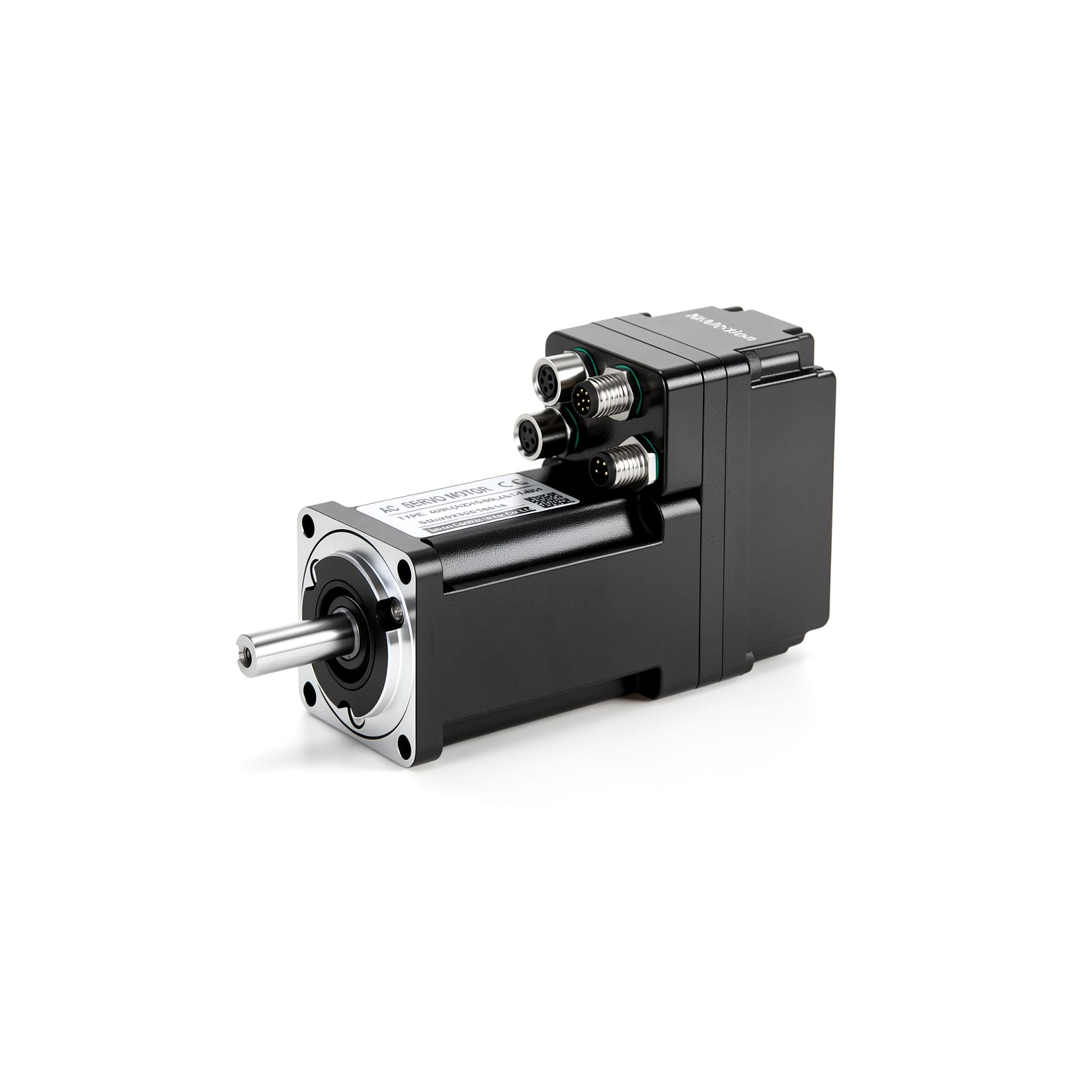
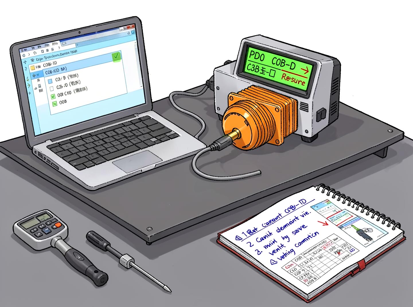
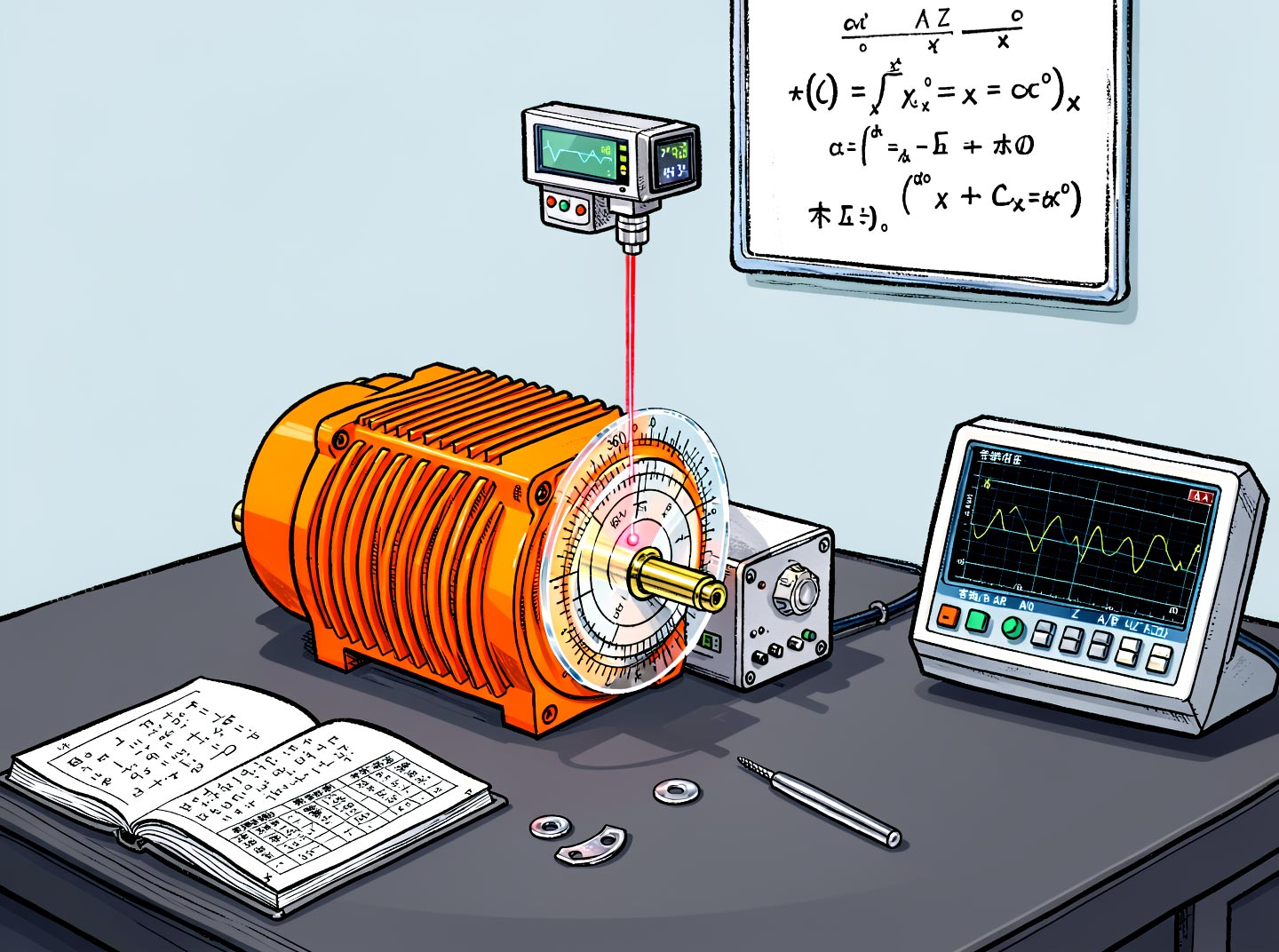
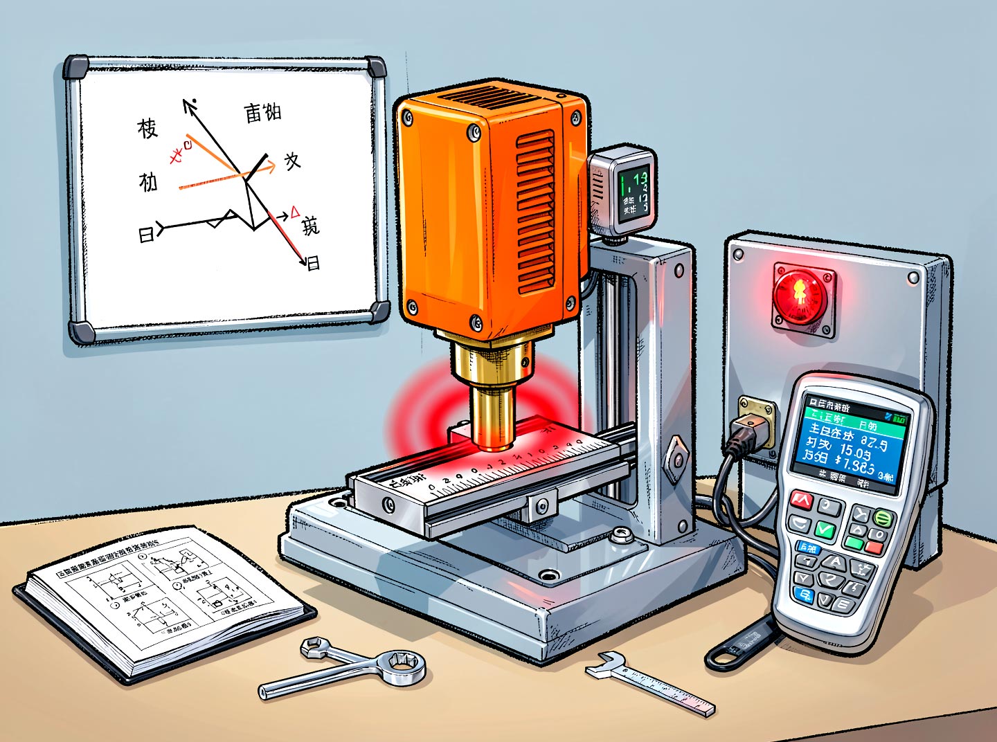
Figure: Servo motor sizing — combining load parameters, transmission mechanism and calculation documents to verify torque and inertia
First Establish the Overall Framework: Servo Sizing Must Satisfy 4 Constraints Simultaneously
Sizing a servo is not just about "is the power enough"; you must pass four checks at the same time:
Torque constraint — peak torque (including acceleration) ≤ motor maximum torque
Speed constraint — maximum running speed ≤ motor rated speed
Inertia constraint — load inertia ratio ≤ allowable value (usually 5:1)
Thermal constraint — effective (RMS) torque ≤ motor rated torque
Many engineers only do check 1, and the motor runs hot under continuous duty; others only do checks 1 and 2, and cannot tune a stable gain. Only when all four pass is the sizing complete.
Step 1: Determine the Mechanical Parameters
First, list the complete mechanical-side data. If any item is missing, all subsequent calculations are castles in the air.
Parameter | Symbol | Description | Common Unit |
|---|---|---|---|
Load mass | m | Worktable + workpiece + fixture | kg |
Transmission type | — | Ball screw / timing belt / rack and pinion / direct drive | — |
Screw lead | PB | Pitch of the screw | mm/rev |
Pulley diameter / gear pitch diameter | D | Rotation→linear conversion radius | mm |
Friction coefficient | μ | Guide friction; rolling guides usually 0.003–0.01 | — |
Mechanical efficiency | η | Screw 0.9–0.95, timing belt about 0.9 | — |
Stroke | L | Single movement distance | mm |
Positioning time | t | Allowed time for the whole move | s |
Acceleration/deceleration time | ta | Usually about 1/3 of positioning time | s |
Vertical axis or not | — | Vertical axes must additionally overcome gravity | — |
Step 2: Calculate the Load Torque
The load torque consists of three parts:
TL = Tfriction + Tgravity + Texternal
2.1 Ball Screw Case
Friction torque (reflected to the motor shaft):
Tf = (μ · m · g · PB) / (2π · η)
Gravity torque (vertical axis):
Tg = (m · g · PB) / (2π · η)
External force torque (e.g., cutting force, thrust):
Te = (Fext · PB) / (2π · η)
where g = 9.8 m/s², and PB is converted to meters.
2.2 Timing Belt / Rack Case
Replace the screw lead PB with 2πr (r is the pulley radius, in meters):
Tf = (μ · m · g · r) / η
2.3 A Complete Worked Example (Ball Screw)
Given conditions: horizontal screw, load mass m = 30 kg, screw lead PB = 10 mm, diameter 20 mm, friction coefficient μ = 0.005, efficiency η = 0.9, stroke 300 mm, positioning time 0.6 s, acceleration and deceleration times 0.2 s each.
① Friction torque
Tf = (0.005 × 30 × 9.8 × 0.01) / (2π × 0.9) = 0.0147 / 5.655 ≈ 0.0026 N·m
Very small — this is why the friction term of a horizontal ball screw mechanism is often ignored; the real dominant term is the acceleration torque.
② Acceleration torque
Maximum speed v = 300 mm / 0.4 s (constant-speed segment) = 750 mm/s
Acceleration a = v / ta = 0.75 m/s / 0.2 s = 3.75 m/s²
Required acceleration force Fa = m · a = 30 × 3.75 = 112.5 N
Acceleration torque reflected to the motor shaft (considering only the load mass):
Ta_load = (Fa · PB) / (2π · η) = (112.5 × 0.01) / (2π × 0.9) = 1.125 / 5.655 ≈ 0.199 N·m
③ Maximum speed required by the motor
n = v / PB × 60 = (750 mm/s ÷ 10 mm/rev) × 60 = 75 × 60 = 4500 rpm
Speed is the hard constraint here — a typical servo has a rated speed of 3000 rpm, so you need a high-speed model or a larger screw lead.
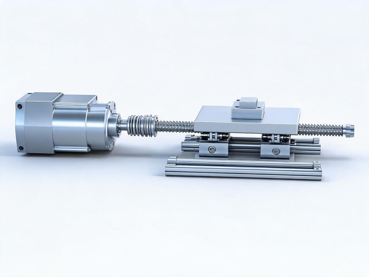
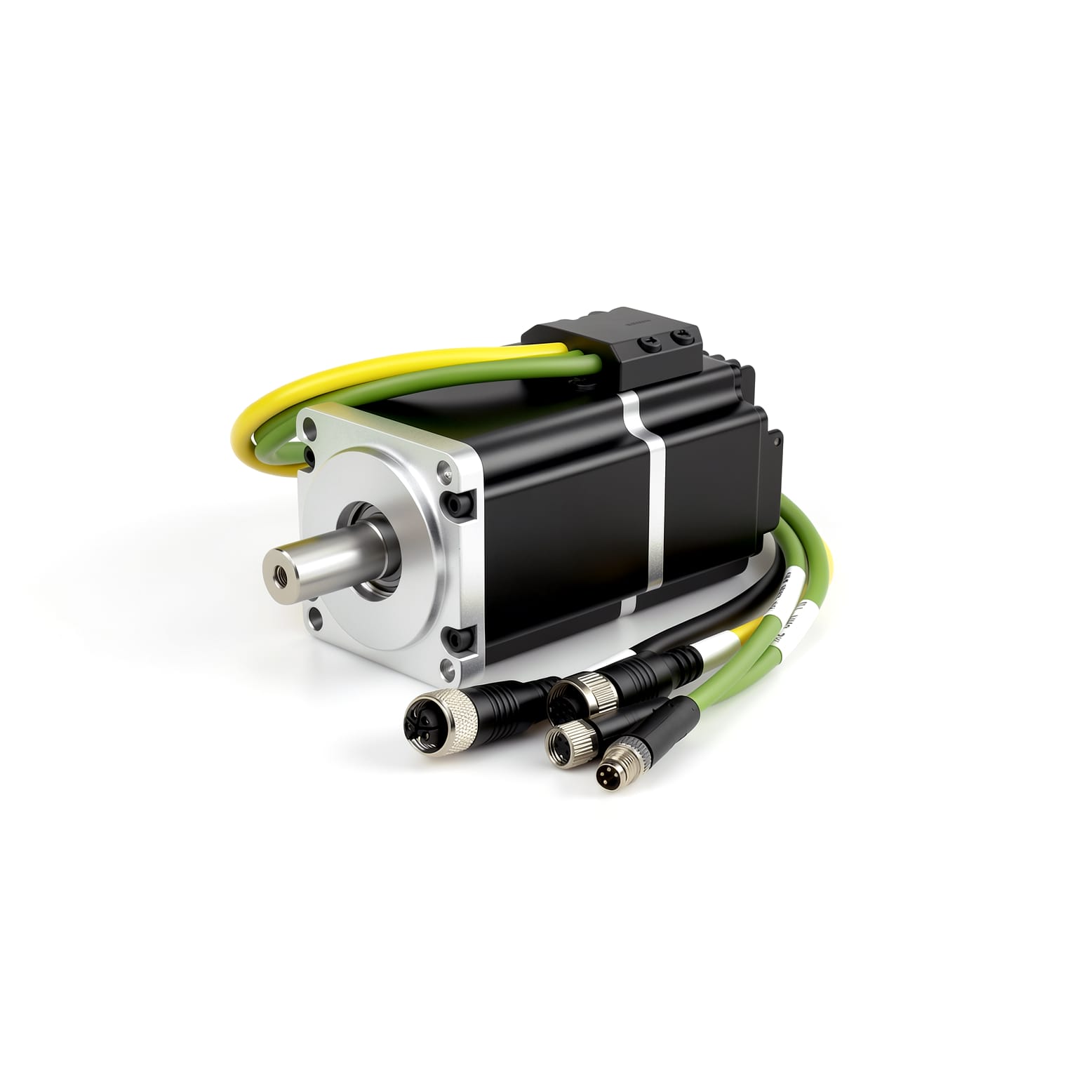
Figure: Ball screw servo transmission mechanism — load torque consists of friction, gravity and external force components
2.4 Key Reminder: Don't Forget to Reflect the Inertia of the Screw and Coupling Themselves
The acceleration torque above only counted the translating load mass. The actual system must also add the moment of inertia of the screw body, coupling, and pulleys. Screw inertia:
Jscrew = (π · ρ · Ls · d⁴) / 32
Steel density ρ ≈ 7850 kg/m³. For a screw with diameter 20 mm and length 400 mm:
Jscrew = (π × 7850 × 0.4 × 0.02⁴) / 32 ≈ 4.93 × 10⁻⁵ kg·m²
This value looks small, but compared with the rotor inertia of a small servo motor (on the order of 10⁻⁵), it is not small and must be included.
Step 3: Reflect the Load Inertia to the Motor Shaft
Inertia of the translating mass reflected to the motor shaft:
Jload = m · (PB / 2π)² (screw)
Jload = m · r² (timing belt / rack)
Continuing the example:
Jtranslating load = 30 × (0.01 / 2π)² = 30 × 2.533 × 10⁻⁶ ≈ 7.6 × 10⁻⁵ kg·m²
Total load inertia:
JL = Jtranslating load + Jscrew + Jcoupling ≈ 7.6 × 10⁻⁵ + 4.93 × 10⁻⁵ + 0.2 × 10⁻⁵ ≈ 1.27 × 10⁻⁴ kg·m²
Step 4: Verify the Inertia Ratio
Inertia ratio = JL / JM (JM is the motor rotor inertia)
Common industry criteria:
Inertia ratio | Rating | Response |
|---|---|---|
< 1:1 | Excellent | Ideal value for high-dynamic-response applications |
1:1 – 3:1 | Good | The vast majority of general equipment |
3:1 – 5:1 | Acceptable | Needs careful gain tuning; response is slower |
5:1 – 10:1 | Large | Difficult to tune, prone to oscillation |
> 10:1 | Too large | Must enlarge the motor or add a gearbox |
Continuing the example, if the candidate motor rotor inertia JM = 0.67 × 10⁻⁴ kg·m² (typical for a 60-frame 200W class):
Inertia ratio = 1.27 × 10⁻⁴ / 0.67 × 10⁻⁴ ≈ 1.9 : 1 ✅ falls in the good range.
The most effective way to reduce the inertia ratio is to add a planetary gearbox. With a reduction ratio i, the load inertia decays by i²:
Jreflected = JL / i²
Adding a gearbox with i = 5 drops the inertia ratio to 1/25, changing it from "barely usable" to "very easy." This is also the fundamental reason planetary gearboxes are widely used in servo systems — they are not just torque multipliers, they are inertia matchers.
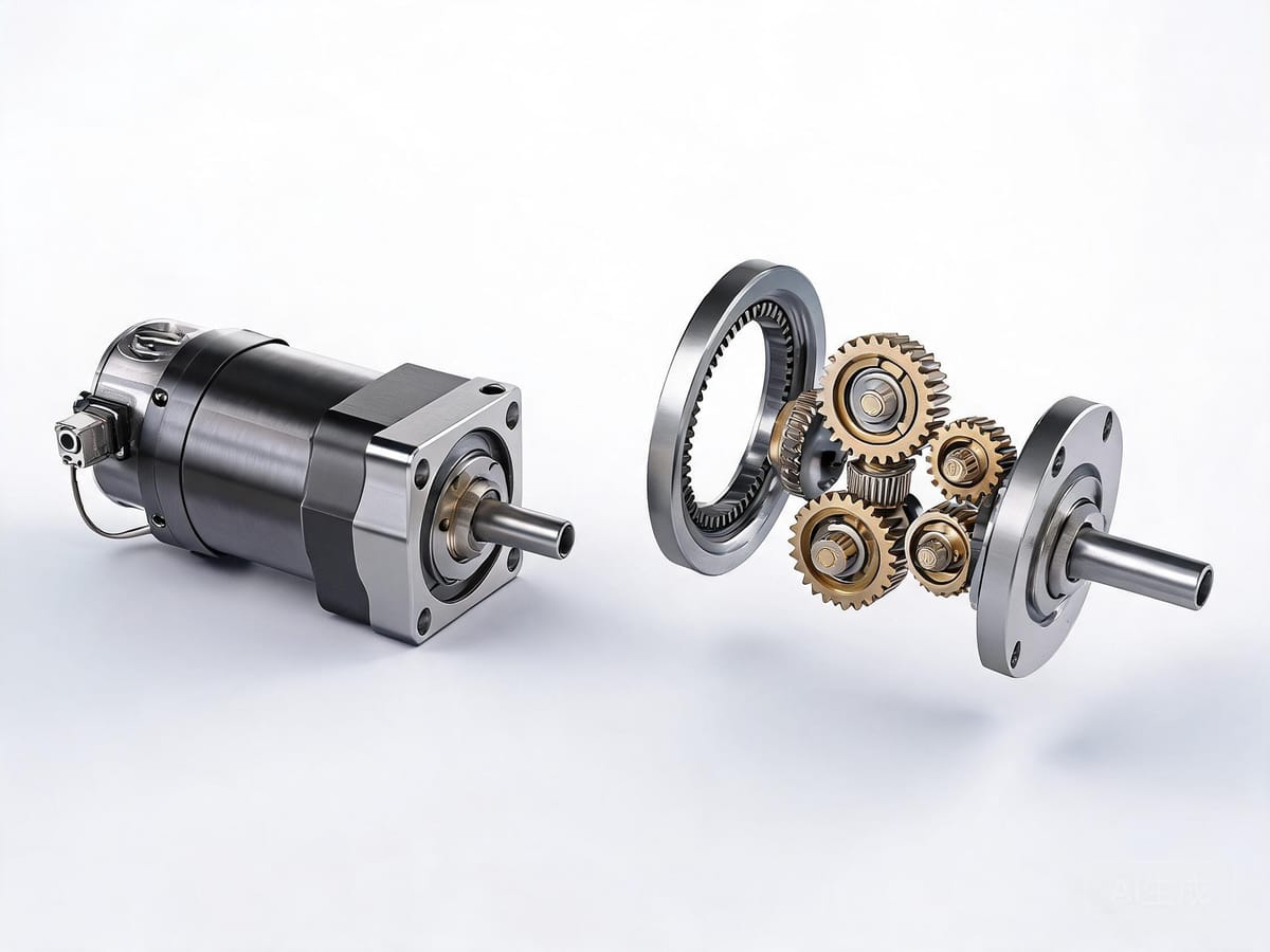
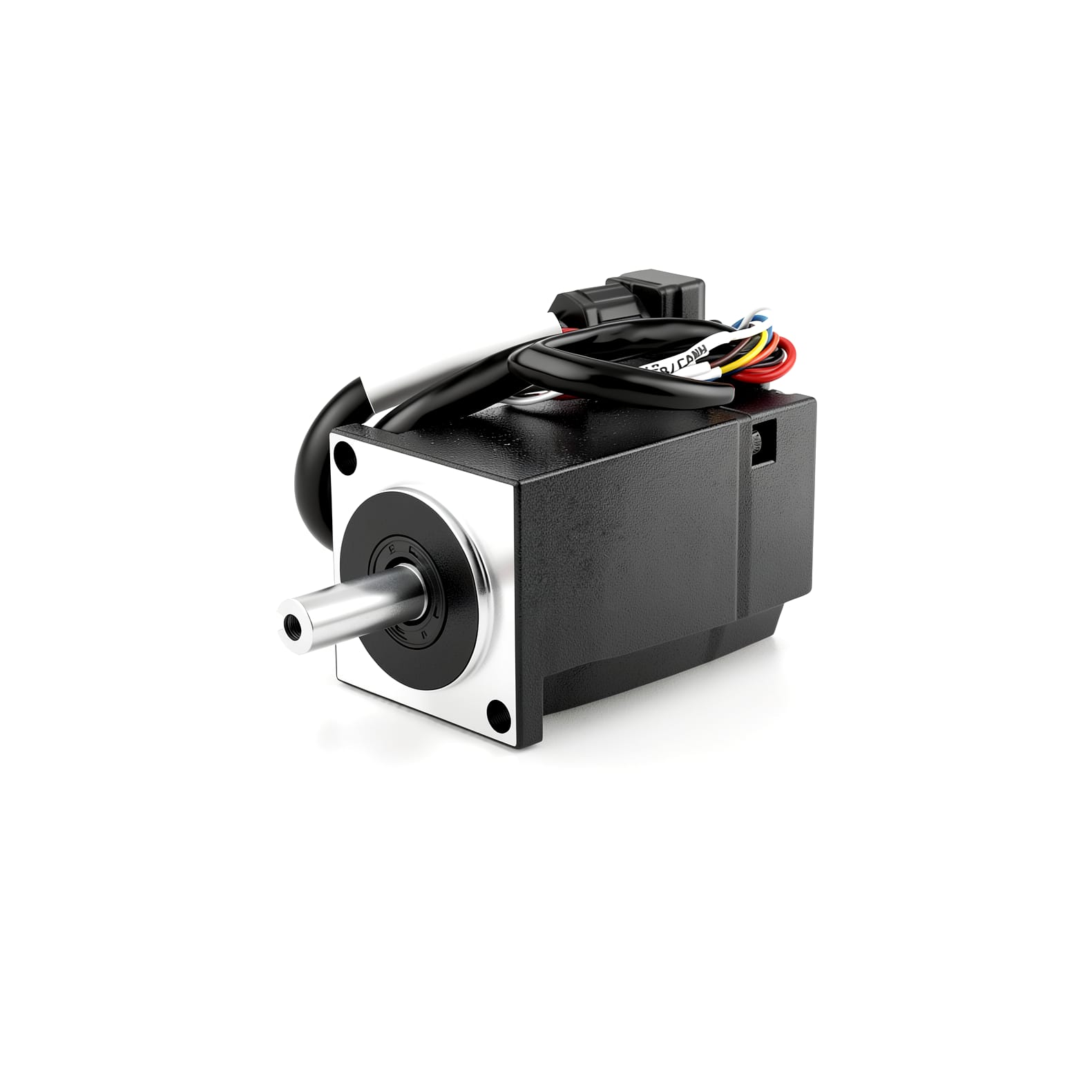
Figure: Planetary gearbox — load inertia decays by the reduction ratio i², the most effective inertia-matching method in servo systems
Step 5: Match the Speed
Confirm that the maximum running speed ≤ motor rated speed, and leave a 10%–20% margin.
The example requires 4500 rpm. If you select a servo rated at 3000 rpm, you must:
Increase the screw lead (e.g., 10 mm → 20 mm, reducing the speed requirement to 2250 rpm), or
Choose a high-speed servo rated above 5000 rpm, or
Reduce speed (extend the positioning time)
Note: above the rated speed the motor enters the constant-power field-weakening region, and the available torque decreases as speed rises — this must be verified against the torque-speed curve.
Step 6: Verify Peak Torque and Effective Torque
Peak Torque
Tpeak = Tacceleration + Tload
The acceleration torque must also include the motor's own inertia:
Tacceleration = (JM + JL) · β , β = angular acceleration = (2π · n) / (60 · ta)
Continuing the example:
β = (2π × 4500) / (60 × 0.2) = 28274 / 12 ≈ 2356 rad/s²
Tacceleration = (0.67 + 1.27) × 10⁻⁴ × 2356 ≈ 0.457 N·m
Tpeak = 0.457 + 0.0026 ≈ 0.46 N·m
If the candidate motor has a rated torque of 0.637 N·m (e.g., Limaisheng PMM60 series 200W/3000rpm parameters), and the maximum torque is 1.9 N·m at 3× — the peak check passes with ample margin.
Effective Torque (Thermal Check) — The Step Most Often Skipped
For cyclic duty with frequent start/stop, calculate the RMS torque over one cycle:
Trms = √[ (T₁²t₁ + T₂²t₂ + … + Tₙ²tₙ) / (t₁ + t₂ + … + tₙ) ]
Criterion: Trms ≤ motor rated torque.
If Trms exceeds the limit, the motor will not alarm immediately, but after several hours of continuous operation it will shut down due to over-temperature protection — this is one of the hardest faults to diagnose on site, because "the no-load test runs perfectly."
Step 7: Confirm the Encoder, Bus and Structural Form
After the calculations pass, finally confirm these engineering details:
How to Choose the Encoder Type
Type | Position after power-off | Homing needed on power-up | Suitable scenarios |
|---|---|---|---|
Incremental | Lost | Yes | Conveyors, general speed control, cost-sensitive |
Single-turn absolute | Retained within one turn | No homing if passive rotation stays within one turn | Index tables, short-stroke mechanisms |
Multi-turn absolute | Fully retained (turns + angle) | Completely homing-free | Robot joints, long-stroke gantries, vertical axes |
Strong recommendation: as long as the equipment has a vertical axis, long stroke, or a process that cannot stop for homing, use a multi-turn absolute encoder. Mechanical multi-turn solutions (gear-train counting) are battery-free and maintenance-free, and have gradually become the standard for a new generation of servos.
How to Choose the Bus Type
Bus | Sync accuracy | Single-frame cycle | Suitable for |
|---|---|---|---|
EtherCAT | < 1 μs | 100 μs class | Multi-axis synchronization, flying shear, robots |
CANopen | — | 1 ms class | Medium-low speed multi-axis, cost-sensitive |
Modbus RTU (RS485) | — | 10 ms class | Simple start/stop or speed command, strong anti-interference, long distance |
Pulse/direction | — | Depends on controller | Single axis, legacy PLC retrofit |
Integrated or Separate
Separate (motor + driver): wide power range, good heat dissipation, centralized mounting, suitable for traditional cabinet solutions;
Integrated (drive-in-one): saves the driver, encoder cable, and cabinet space; wiring drops from a dozen-plus cables to 2–3, especially suitable for multi-axis and mobile equipment (AGV/AMR) and space-constrained applications.
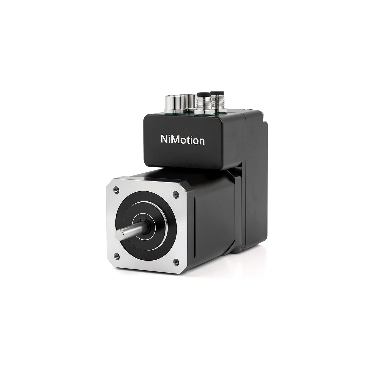
Limaisheng NiMotion's PMM/PSM integrated servo motors use this form: 48V supply, 200W rated power, 3000 rpm rated speed, 0.637 N·m rated torque, built-in 25W/35W braking resistors, FOC field-oriented control + SVPWM, integrated 2500-line encoder, IP65 protection, and optional CANopen / RS485 / EtherCAT(COE) communication.
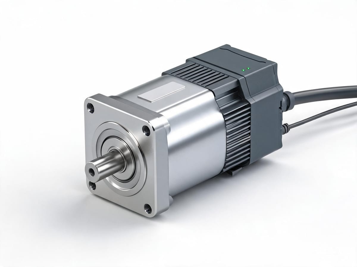
Figure: Integrated (drive-in-one) servo motor — driver, encoder and communication integrated into the motor body; only 2–3 cables are needed
Servo Sizing Quick-Reference Sheet
① List all mechanical parameters (mass, lead, stroke, time, friction, vertical axis or not)
② Calculate load torque T_L = T_friction + T_gravity + T_external
③ Calculate load inertia J_L (translating mass + screw + coupling, all reflected to the motor shaft)
④ Verify inertia ratio J_L / J_M  ≤ 5 (ideal ≤ 3)
⑤ Verify maximum speed n_max ≤ rated speed × 0.9
⑥ Verify peak torque ≤ maximum torque; verify T_rms ≤ rated torque (thermal check!)
⑦ Decide encoder (incremental/single-turn/multi-turn absolute) + bus + structural form