
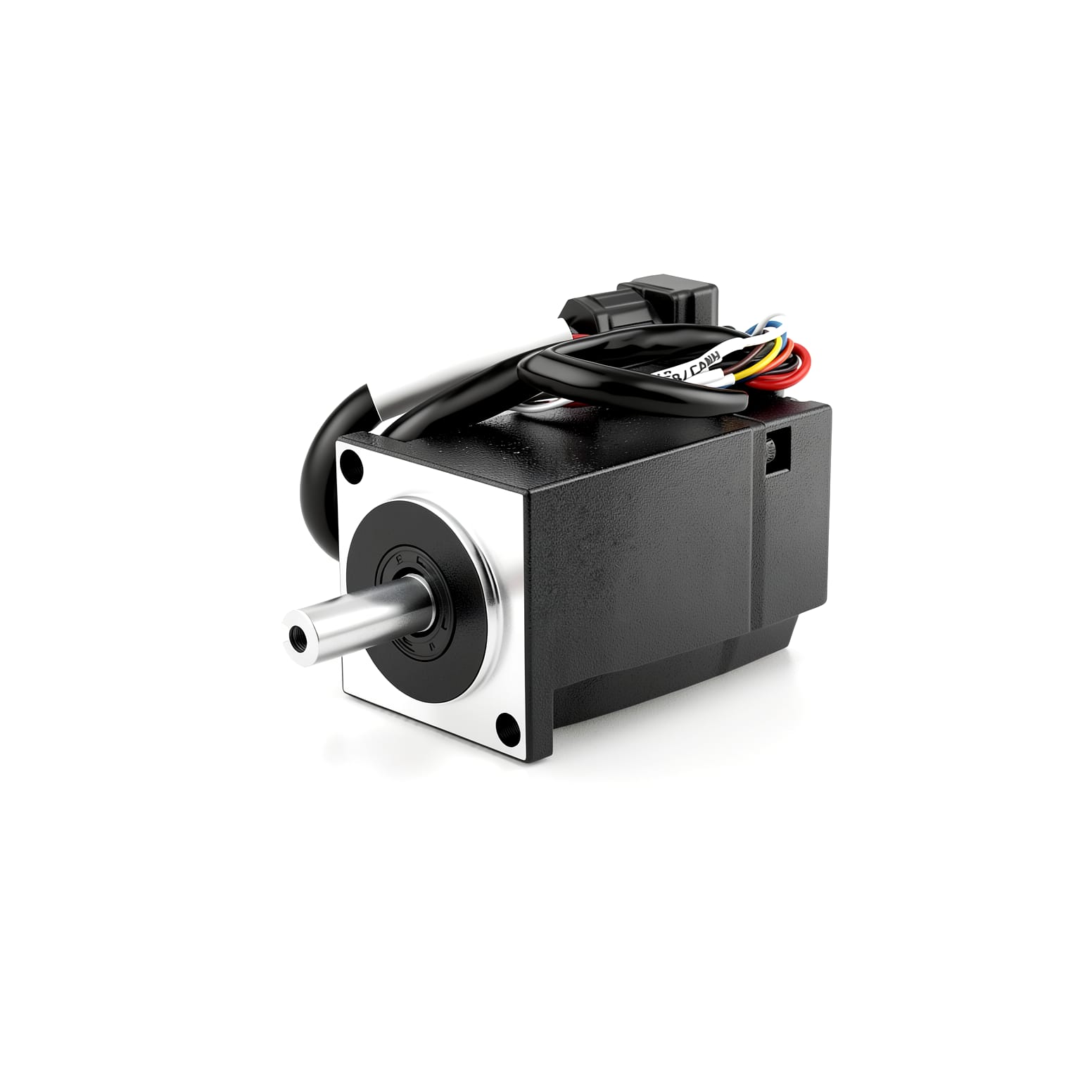
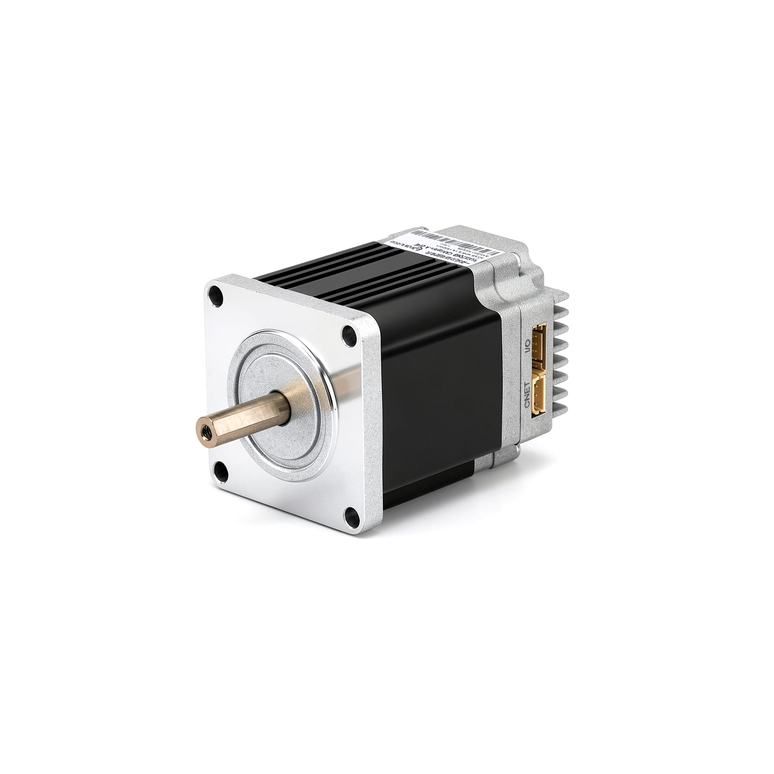
PMMP40L Integrated IP65 Protection DC Servo Motor
Cost-effective 40mm flange integrated servo motor with IP65 high protection rating – integrates drive, control, and I/O, redefining traditional servo systems. Simplifies wiring, saves space, and delivers smarter integrated solutions for a wide range of compact automation equipment.
Features
- IP65 protection rating
- Cost-effective, low-cost design
- More compact size
Models & Specifications
| Specifications | PMMP4010B-485-L-0HE | PMMP4010B-CANopen-L-0HE |
|---|---|---|
| Flange Size | 40mm | 40mm |
| Brake | No Brake | No Brake |
| Encoder type | 17-bit single-turn absolute magnetic encoder | 17-bit single-turn absolute magnetic encoder |
| Rated Speed | 3000 rpm | 3000 rpm |
| Rated Power | 100 W | 100 W |
| Rated Voltage | 24 VDC | 24 VDC |
| Inertia | 6.2×10^-6 kg·m² | 6.2×10^-6 kg·m² |
| Voltage Range | 12-52 | 12-52 |
| Protection Level | IP65 | IP65 |
| STO Function | No | No |
| Body Length | 67.7 mm | 67.7 mm |
| Weight | 0.43 kg | 0.43 kg |
| Rated Current | 6.5 A | 6.5 A |
* Scroll horizontally within the table area when the content is wide.
Specifications
| Shaft Diameter | Φ8 |
| Drive Mode | Adopting FOC magnetic field orientation control technology and SVPWM |
| Encoder | 17-bit single-turn absolute encoder (multi-turn absolute counting, automatic storage upon power failure) |
| CiA402 Mode | PP, VM, PV, PT, HM, IP, CSP, CSV, CST |
| NiMotion mode | PP、VM、PV、PT、HM、IP、CSP、CSV、CST |
| Control Modes | CiA402 Mode,Manufacturer Mode |
| External Control Interface | DI – Non-isolated NPN Input,DI – Non-isolated PNP Input,DI – Non-isolated Switch Input,DO – Non-isolated MOSFET Output |
| DI (Digital Input) | Quantity: 3; Non-isolated; Pull-up configured via object 2003h:15h; High level: 12–24V, low level: 0–0.5V; Supports NPN (pull-up enabled) and PNP; Configurable function: Can be used as a switch or as a pulse input channel. |
| DO (Digital Output) | Quantity: 1; Maximum load current: 0.5A; Configurable functions: 1. General DO port; 2. Motor run/stop; 3. Target reached; 4. Alarm output (when the motor status meets the above conditions, the DO switching state changes). |
| DX (Digital Input / Output) | - |
| AI (Analog Input) | - |
| Operating Temperature | 0°C to 40°C |
| Operating Altitude | <1000m |
| Fault Alarm | Overvoltage, undervoltage, overtemperature, locked rotor, overload, overspeed |
| Servo Function | Soft limit, gain switching, S-curve planning, vibration suppression, parameter identification, online upgrade |
Torque-Speed Characteristics
PMMP4010B-CANopen/485-L-XX
Product Details
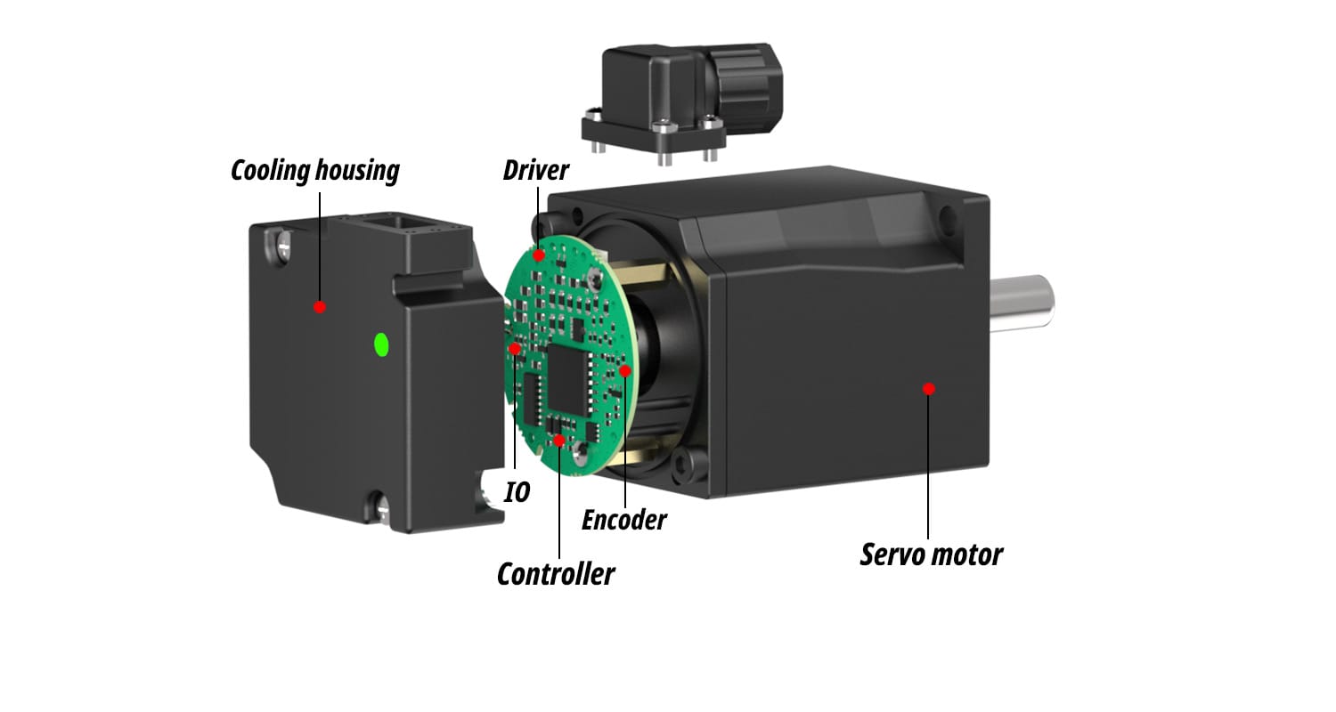
Nimotion PMMP40L waterproof servo machine integrated servo motor, highly integrated development concept, set permanent magnet synchronous motor, magnetic encoder, servo drive and controller in one, the use of FOC field oriented control technology and drive control technology, with IP65 protection level certification. The latest upgraded oil seal protection can effectively prevent water splash and dust intrusion, with stronger work adaptability, excellent performance and higher reliability. Adopt a highly integrated waterproof servo machine integrated development concept, would be a perfect fusion of the servo motor and drive control system significantly save equipment takes up space. It supports bus control, allowing for control with just one bus.
Product Features
Fault alarm
IP65 protection
Simple and convenient wiring
Compact
Highly integrated design
17-bit magnetic encoder
Soft limit
Curve Planning
Vibration suppression
Waterproof servo all-in-one machine
Integrated Design Philosophy
Highly integrated design
Integrates permanent magnet synchronous motor, encoders, servo drives and controllers into a single compact unit, so no external drive is required. Compared with conventional separated solutions it saves considerable installation space, needs less wiring, and makes commissioning and maintenance easier.
Advanced Drive Algorithm
Adopts FOC (field-oriented control) and SVPWM for smooth torque output, excellent low-speed performance and lower operating noise and vibration.
High Precision Encoder Feedback
Built-in 17-bit encoder provides real-time position and speed feedback for more accurate closed-loop control, ensuring smoother operation and more accurate positioning.
Multi-bus communication support
Supports CANopen and RS485 communication, allowing quick connection to mainstream PLCs, motion controllers and host systems, with flexible networking and easy expansion.
Multiple Control Modes
Supports multiple control modes and standard CiA 402 motion modes (PP, PV, HM, CSP, etc.), switchable via fieldbus, pulse train, analog input or digital I/O to suit different host systems.
Wide Voltage Input
Wide input voltage range of 12-52 VDC, suitable for various power-supply environments and giving greater flexibility in system integration and retrofitting.
Digital Inputs / Outputs
Built-in digital inputs and outputs (DI/DO) that can be configured for enable, forward/reverse limit switches, home sensor, alarm output, brake control and more, allowing direct interfacing with sensors and PLCs without additional I/O modules and simplifying field wiring.
Integrated High-precision Encoder
An integrated high-resolution absolute encoder provides real-time rotor position and speed feedback for full closed-loop control. Multi-turn absolute versions store the position when power is lost, so no re-homing is required after power-up, giving more accurate positioning and smoother low-speed operation.
Homing and Origin Setting
Multiple homing (origin return) modes with configurable homing direction, speed and origin offset, allowing the mechanical origin to be re-established quickly after power loss or an abnormal stop and ensuring repeat positioning accuracy.
Gain Switching
Several gain sets can be stored and switched, with online auto-tuning available. Gains can be changed automatically or manually according to load inertia and operating speed, balancing fast response with smooth low-speed operation for quicker commissioning.
16-segment Position / Velocity & S-curve Planning
A built-in 16-segment position and velocity instruction function combined with S-curve acceleration/deceleration planning enables smooth multi-point positioning with reduced start/stop shock and mechanical vibration, improving cycle time and motion smoothness.
Resonance Suppression
Resonance suppression automatically identifies and sets mechanical resonance frequencies and uses notch filtering to suppress mid- and high-frequency resonance, reducing operating noise and improving positioning stability and path accuracy.
Low-frequency Vibration Suppression
Low-frequency vibration suppression compensates the residual sway of long arms, belts and other flexible loads, giving faster settling and more stable positioning in high-speed point-to-point applications.
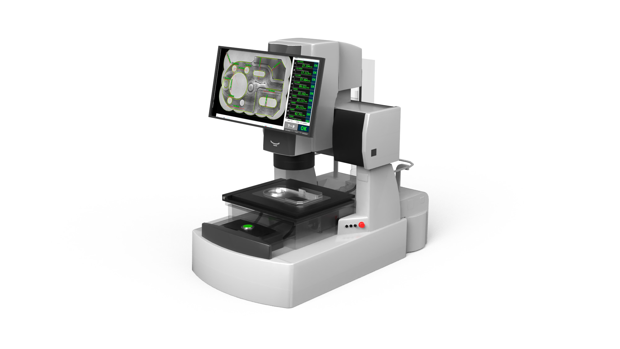
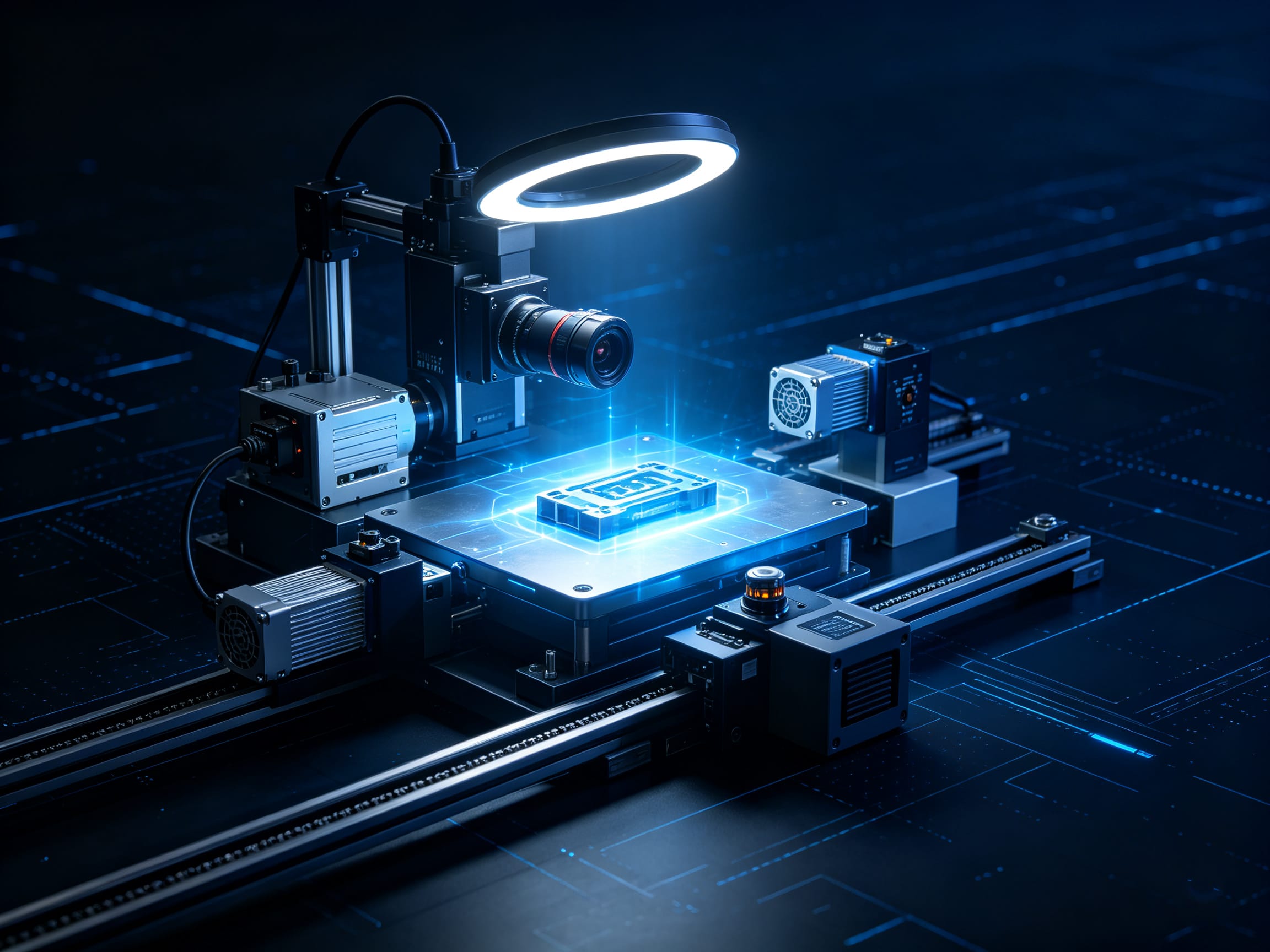
Flash tester equipment application
The integrated design significantly reduces the number of external cable connections, making the integration of the optical path system and the motion module more compact and tidy. This is particularly suitable for the application requirements of flash testers that demand a high degree of internal space compactness and are sensitive to cable interference. It effectively enhances the system's anti-interference ability and operational stability.
Downloads
Companion Products
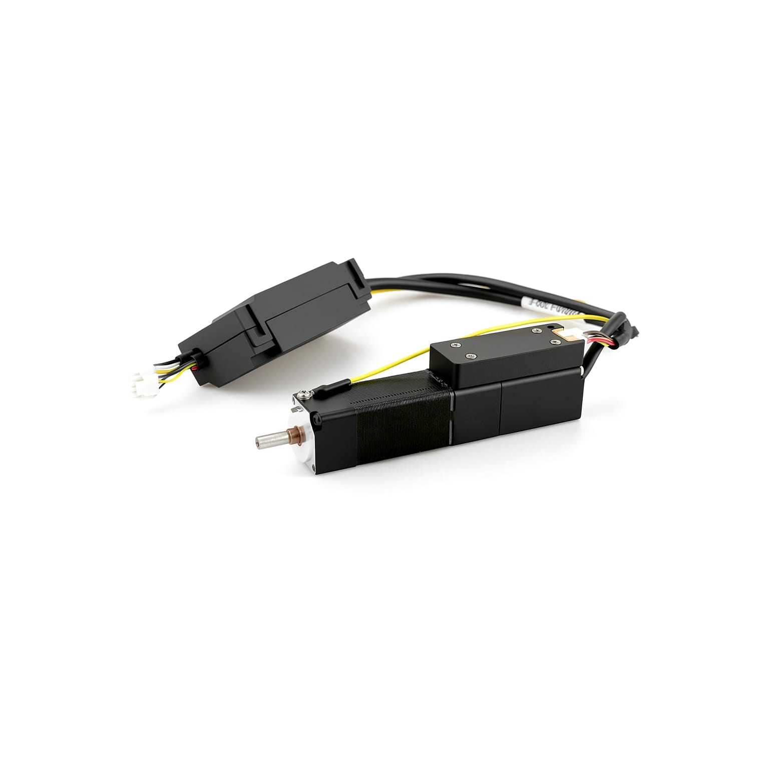
USB to CAN converter with isolation, IP65 protection, and secondary development SDK support.
USB to RS485 converter with active termination, isolation, IP65 protection, and secondary development SDK support.
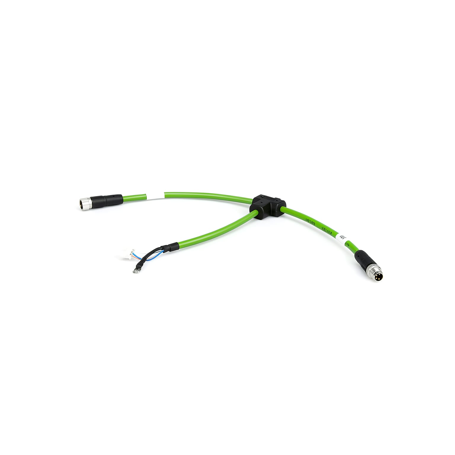
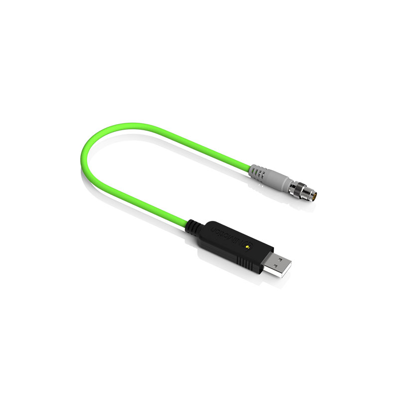
Communication cable for NiMotion integrated motors.
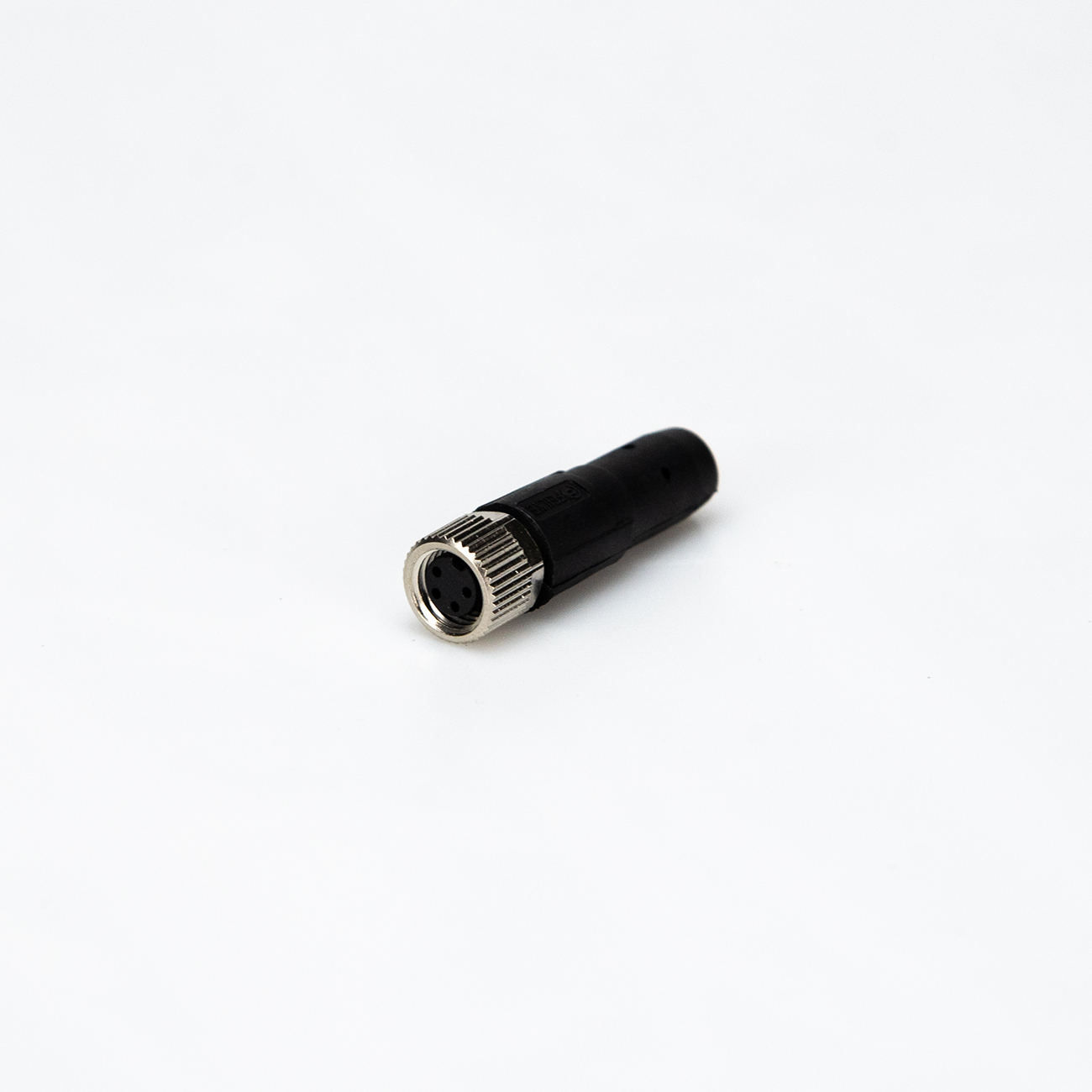
FAQ
2‑phase motors are less expensive but exhibit more vibration at low speeds and have a steeper torque drop at high speeds. 5‑phase motors have lower vibration and better high‑speed performance – they can run 30‑50% faster than 2‑phase motors, and can replace servo motors in some applications. For general cost‑sensitive uses, choose 2‑phase; if vibration and high‑speed performance are critical, choose 5‑phase.
Microstepping is essentially an electronic damping technique, primarily designed to reduce or eliminate low‑frequency vibration. Improved positional resolution is a secondary benefit. Different manufacturers’ microstepping drivers can vary greatly in accuracy, and higher microstepping numbers are harder to control precisely.
This is due to the motor’s pull‑in rate – the maximum pulse frequency at which it can start from standstill without losing steps. If the pulse frequency exceeds this rate, the motor cannot start properly and may lose steps or stall. The solution is to use an acceleration ramp: start at a low frequency and gradually increase to the target high frequency. Integrated stepper motors allow you to set acceleration and deceleration parameters freely.
When the motor rotates, the inductance in each phase winding generates a back‑EMF. The higher the frequency, the greater the back‑EMF, which reduces the phase current and thus lowers the torque.
Excessive temperature can demagnetise the magnetic material, reducing torque and causing step loss. The demagnetisation point is generally above 130°C, some up to 200°C. Therefore, a surface temperature of 80‑90°C is perfectly normal for a stepper motor. The most common insulation class is Class B, with a rated operating temperature up to 130°C.
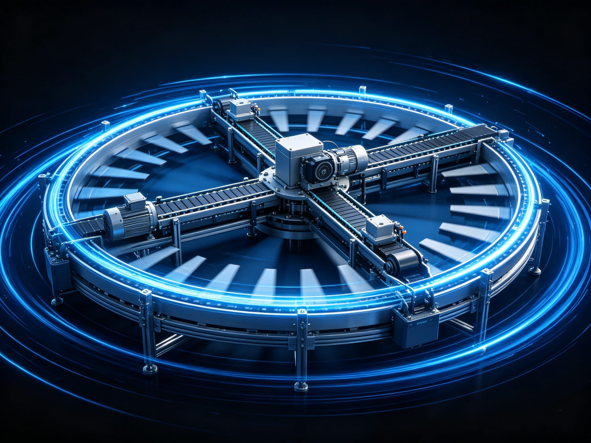
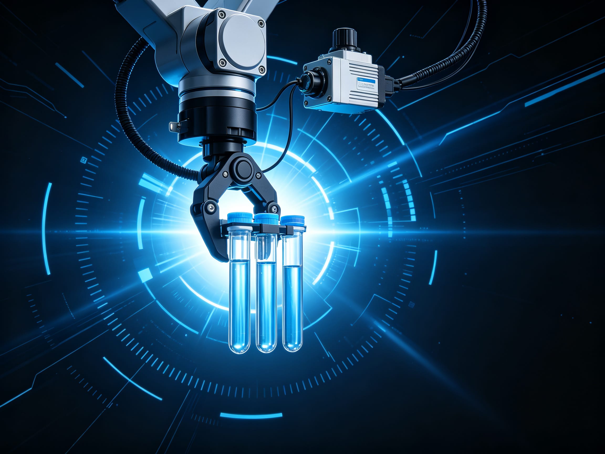
Applications
Discover how this product is applied across various industrial automation scenarios.




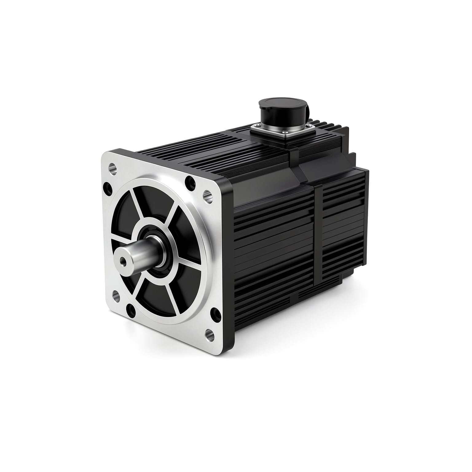
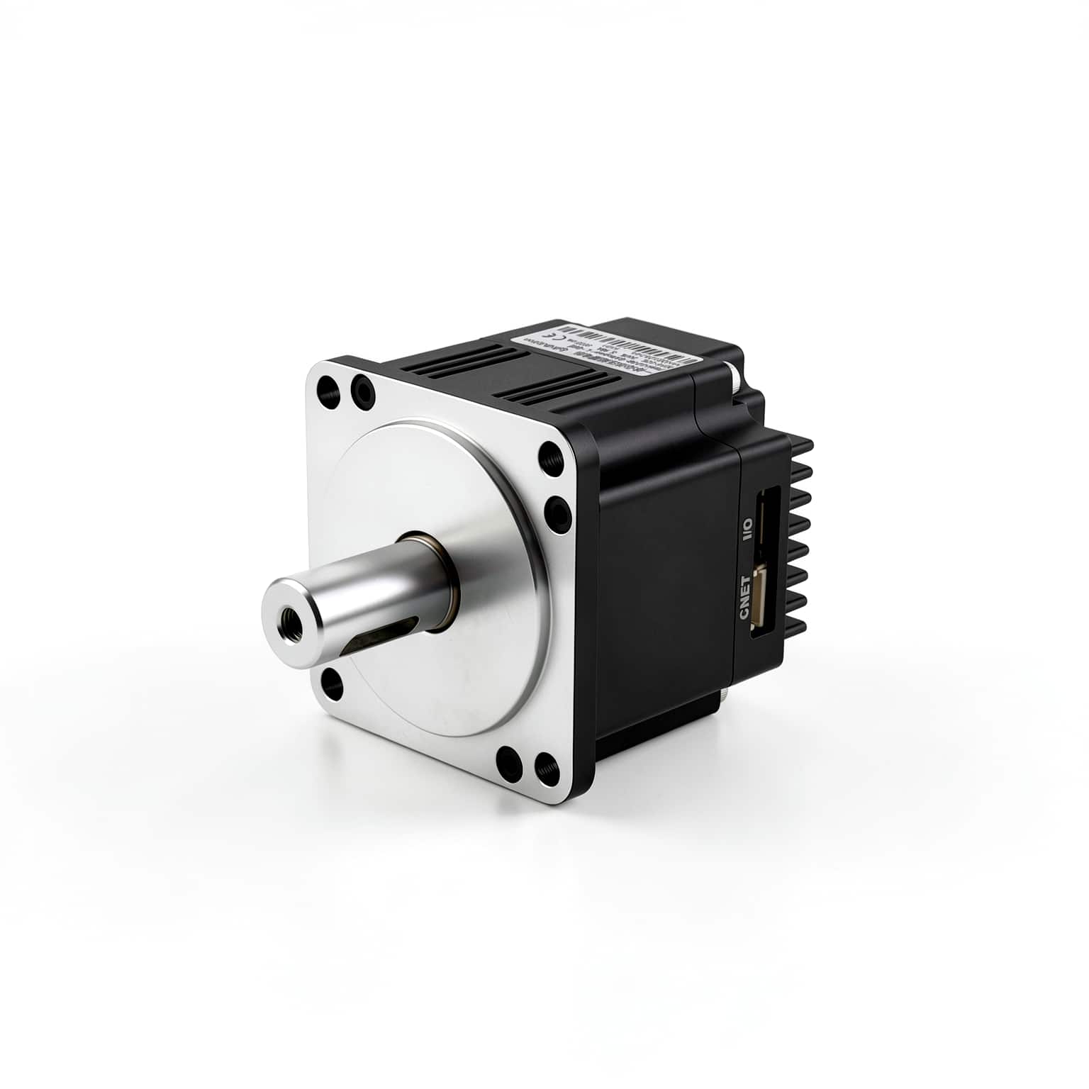
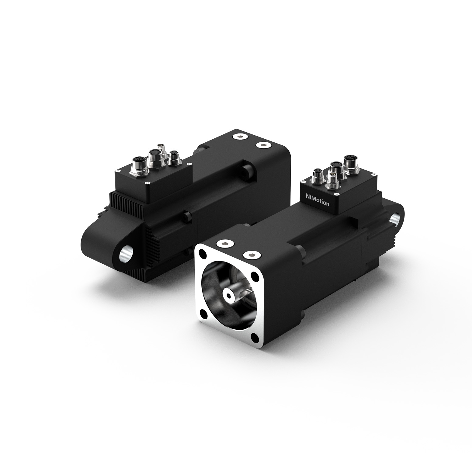
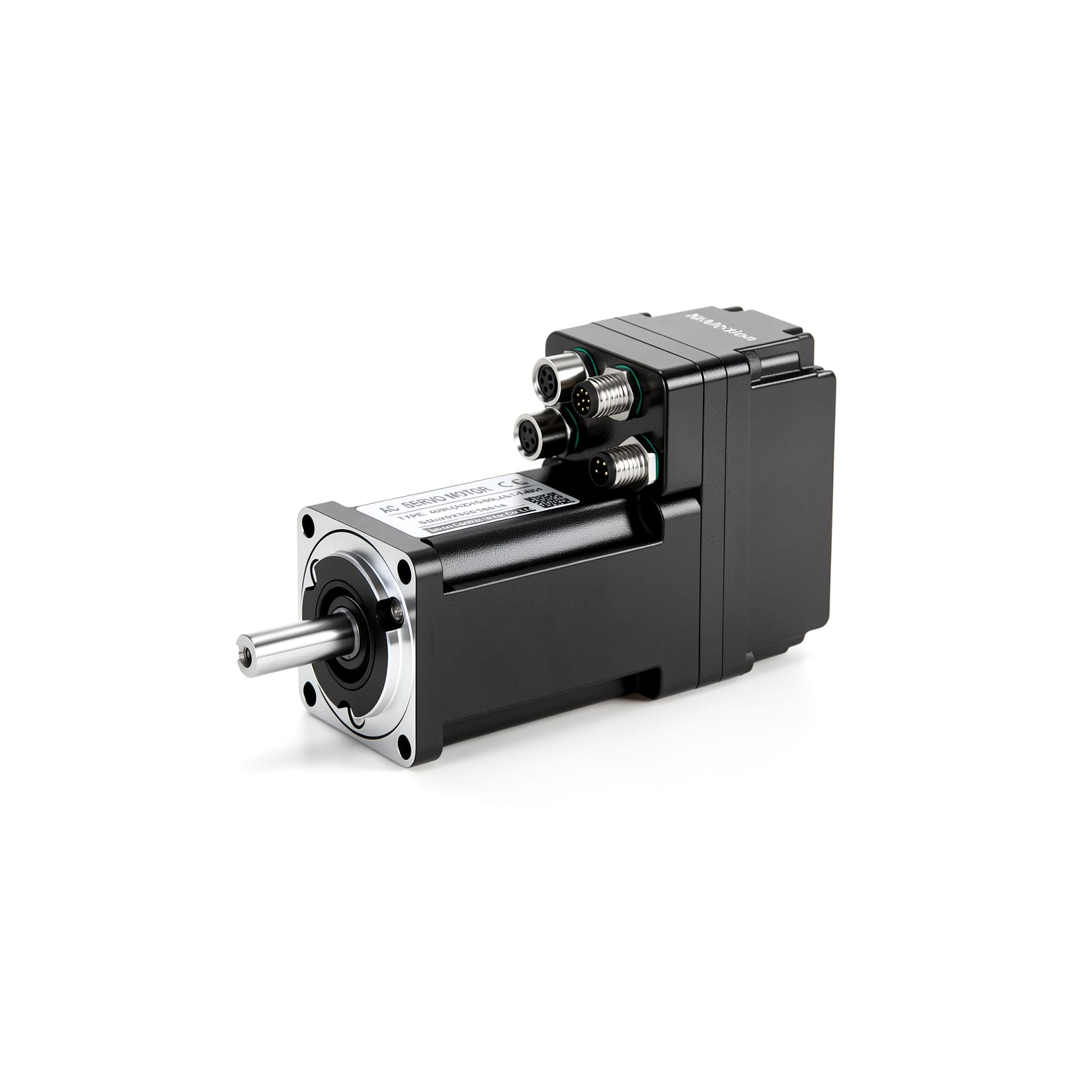
Compatible Products
Build complete and reliable solutions with our compatible products.
Technical Resources
Technical guides, application notes, and more to help you get the most out of the product.
Ready to start your automation project?
Talk to our engineers and get a customized motion control solution within 24 hours.
Typical response time: 24 hours