NiMotion Releases the NGM20L Screw-Driven Electric Parallel Gripper: 150N Grip Force Fills the Mid-Load Gap
What is the NGM20L?
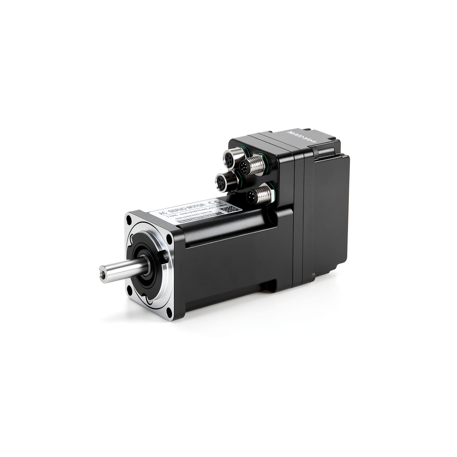
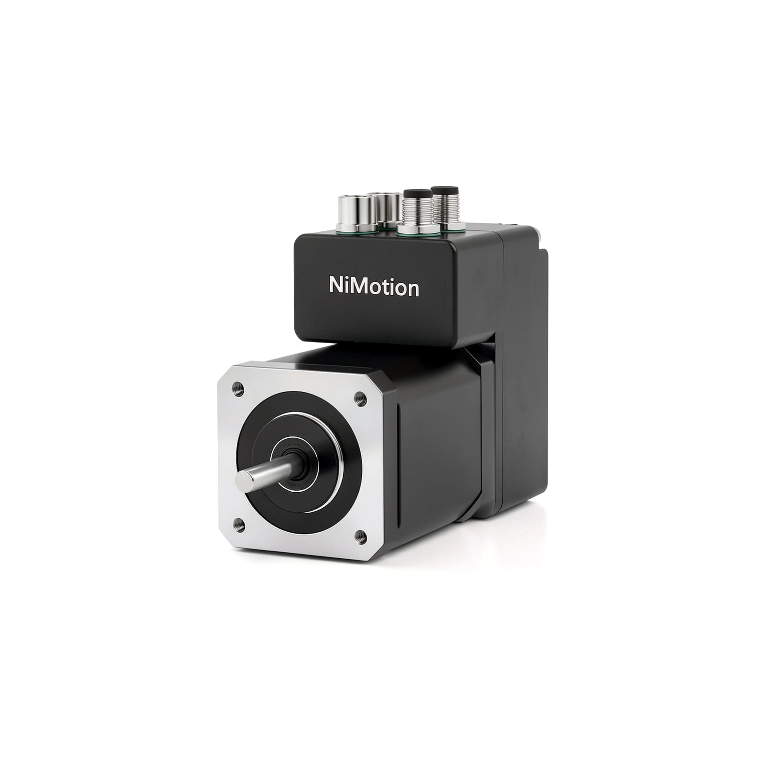
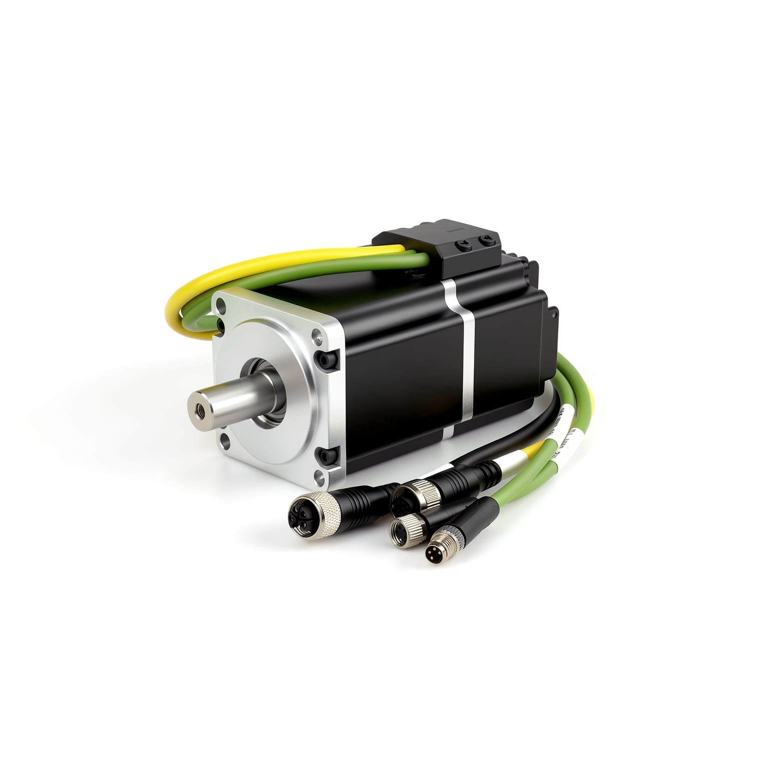
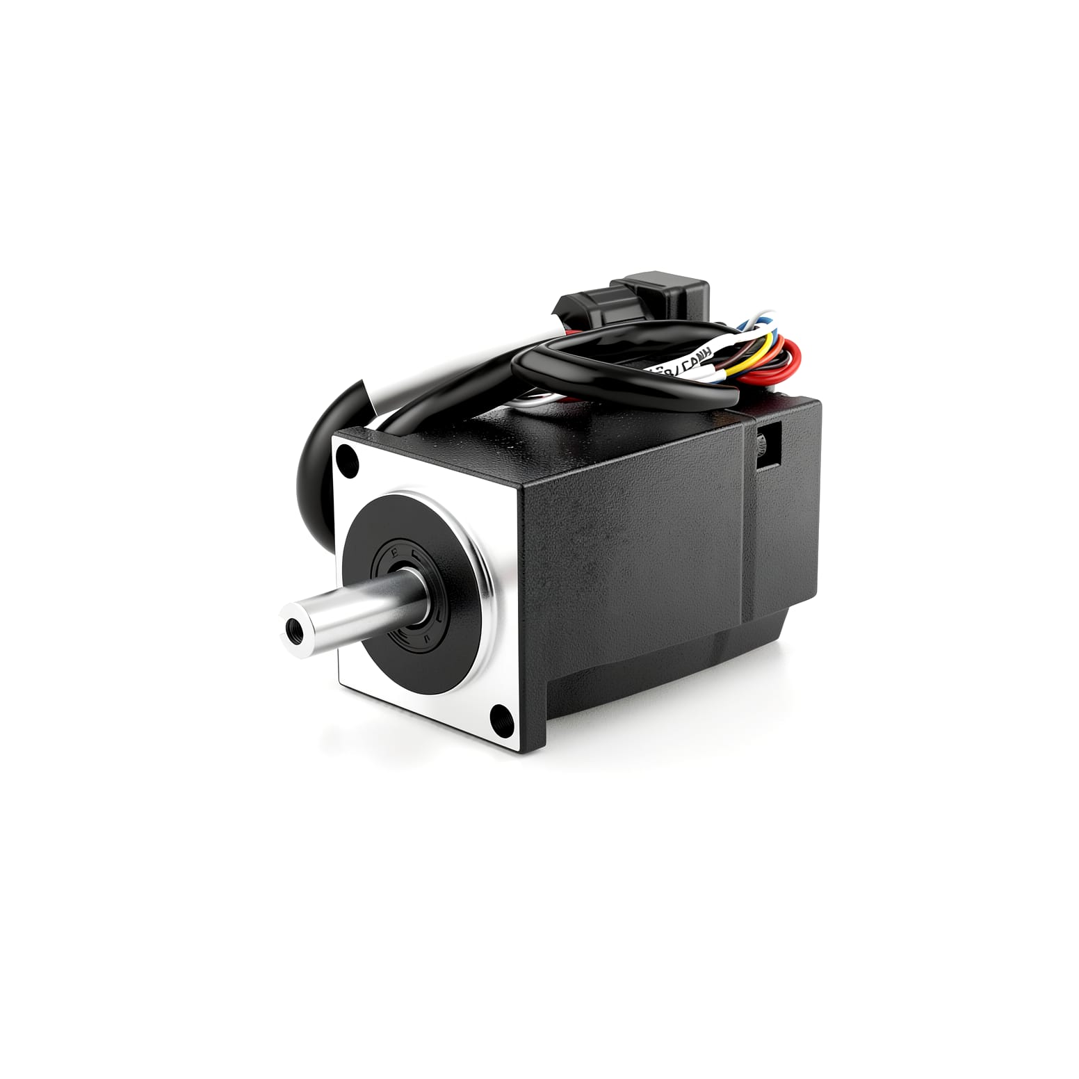
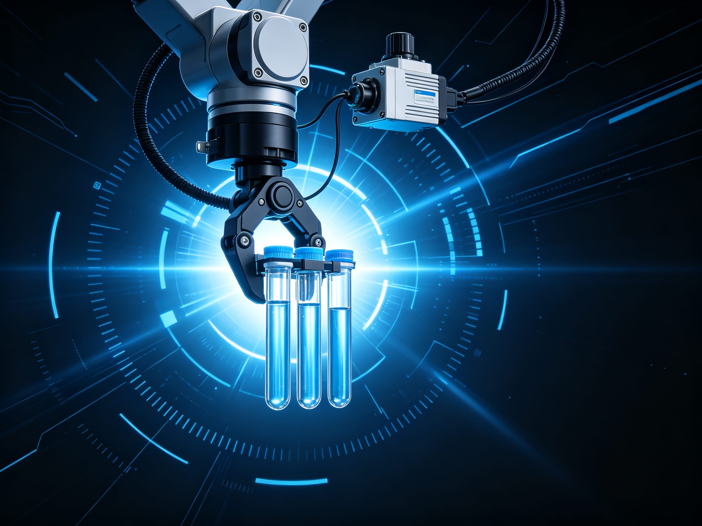
NiMotion has released the NGM20L series screw-driven electric parallel gripper — a rated grip force of 150N, total stroke of 20mm, 0.5s single-direction stroke time, and a 42mm base width. It integrates the STM42M integrated stepper-servo motor, a 17-bit single-turn absolute magnetic encoder, drive, controller, and I/O modules into a single body, supporting both Modbus RTU (RS485) and CANopen buses — wiring is just one bus cable plus one power line.
Which tier does it fill?
In NiMotion's electric gripper line, the rack-type NGM18 covers 6–10N, the NPGM18 servo version 8N, and the screw-type NGM12L 40N. The NGM20L fills the mid-load tier at 150N, targeting scenarios that previously fell back to DIY "motor + screw + rail + drive" builds: positioning and handling of small parts, pre-clamping before fixture press-fitting, and workpiece holding in test equipment.
One-line selection rule: For grip force between 40–150N with space for a 42mm base — and if you want less wiring and less commissioning — evaluate the NGM20L first. If cycle time is critical and load ≤10N, look at NGM18/NPGM18. If you need full CiA402 mode control with lighter loads, look at NGM12L.
1. Positioning: the gripper line adds a "middleweight"
The electric gripper market has long had a selection gap: the light-load tier (10–50N) is crowded, suited to electronic components and connectors. But once workpieces reach several hundred grams and need 100N+ of grip force, integrated electric gripper options thin out sharply, forcing many projects back to a "motor + screw + rail + drive" build-it-yourself approach.
The NGM20L targets exactly this tier. Per the official brochure, it delivers a 150N rated grip force, 20mm total stroke, and 0.5s single-direction stroke time. Combined with the torque characteristics of the STM42M integrated stepper-servo motor, it covers scenarios that previously required custom gripping mechanisms — positioning and handling of small parts, pre-clamping before fixture press-fitting, and workpiece holding in test equipment, for example.
From a product-line perspective, Limaisheng's electric gripper matrix now forms a three-tier layout:
Series | Drive mechanism | Rated grip force | Positioning |
|---|---|---|---|
NGM18 (NGM1806/1810) | Linear rail + rack & pinion | 6–10N | Ultra-compact, high cycle rate |
NPGM18 (NPGM1808) | Linear rail + rack & pinion | 8N | Servo version, high cycle rate |
NGM12L (NGM1240) | Screw + gripper jaws | 40N | Compact screw-driven |
NGM20L (NGM20F0) | Screw + gripper jaws | 150N | Mid-load screw-driven (new) |
2. Integrated architecture: five-in-one
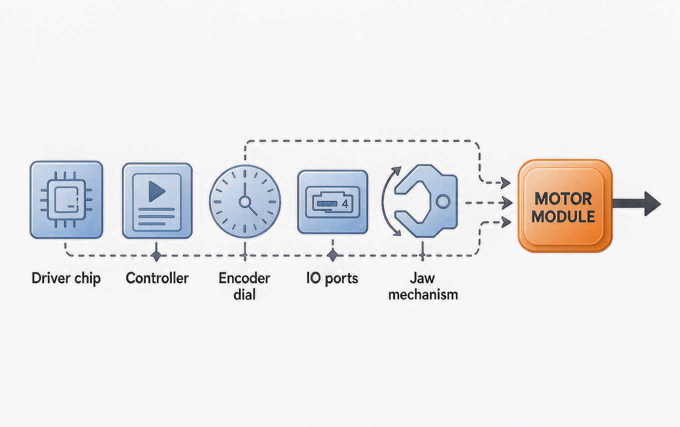
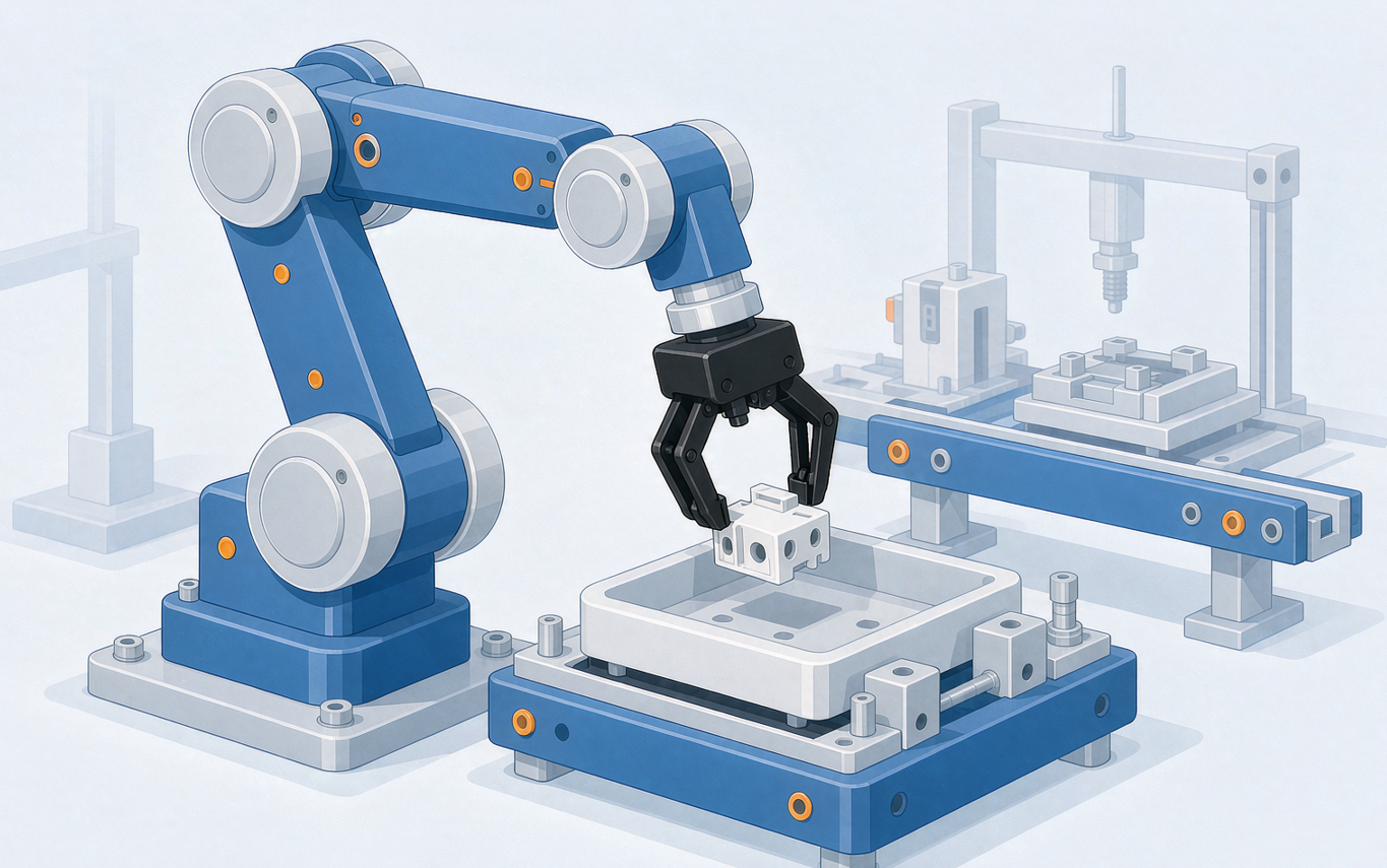
The NGM20L continues NiMotion's "integrated drive-and-control" approach. Per the brochure, it integrates the STM42M integrated screw motor, gripping mechanism, 17-bit encoder, drive, controller, and I/O modules into one unit. For equipment engineers, this brings three direct benefits:
Less wiring: a split solution needs motor power cables, encoder cables, and drive control cables; the NGM20L needs only a power line plus one RS485 or CANopen bus.
Less commissioning: motor and drive are matched at the factory; grip stroke and force are set via bus parameters or I/O triggers — no on-site current-loop tuning.
Less space: with a body of 160×97.4×42.3mm and 1000g weight, it mounts directly on multi-joint robot arms or compact modules.
The encoder deserves attention: a built-in 17-bit single-turn absolute magnetic encoder with multi-turn counting and power-loss position storage. After a power cycle the gripper does not need to re-home — a direct cycle-time gain for lines with frequent start-stops.
3. Control: dual bus + three execution modes
The NGM20L supports Modbus RTU (RS485) and CANopen; model NGM20F0 is versioned by communication type. It also provides 3 NPN digital inputs (5–24VDC logic) and 1 open-collector DO output (max 100mA@30VDC), configurable as a general DO, motor run/stop, target-reached, or alarm output.
Three execution modes cover different integration depths, from "PIO direct trigger" to "full bus control":
Mode | Trigger | Typical use |
|---|---|---|
PIO mode | DI signals directly trigger preset actions | PLC gives switching signals only — the shortest path to retrofit a pneumatic gripper |
Single execution | Command triggers one open/close | Simple pick-and-place |
Loop execution | Reciprocates over the set stroke | Continuous loading/unloading |
The product also inherits the full integrated-motor feature set: fault diagnosis and reset, soft limits, gain switching, resonance suppression, low-frequency suppression, parameter save/restore, and online upgrade. Protections cover over-voltage, under-voltage, over-temperature, stall, storage fault, over-travel detection, and home-return timeout.
4. Key specifications at a glance (NGM20L / NGM20F0)
Item | Specification |
|---|---|
Motor platform | STM42M integrated stepper servo (42mm base width) |
Drive mechanism | Screw + gripper jaws |
Rated grip force | 150N |
Total stroke | 20mm |
Single-direction stroke time | 0.5s |
Rated voltage / current | 24VDC (input range 16–30VDC) / 1A |
Encoder | 17-bit single-turn absolute magnetic encoder (multi-turn counting, power-loss storage) |
Control technology | FOC field-oriented control + SVPWM |
Communication | Modbus RTU (RS485) or CANopen |
Execution modes | PIO / single execution / loop execution |
Allowable load torque | MX: 6N·m; MY: 3N·m; MZ: 3N·m |
DI / DO | 3 NPN inputs / 1 open-collector output (100mA@30VDC) |
Dimensions / weight | 160×97.4×42.3mm / 1000g, no brake |
Protection rating | IP20 |
Operating environment | 0–40℃, 10–85%RH non-condensing, altitude <1000m |
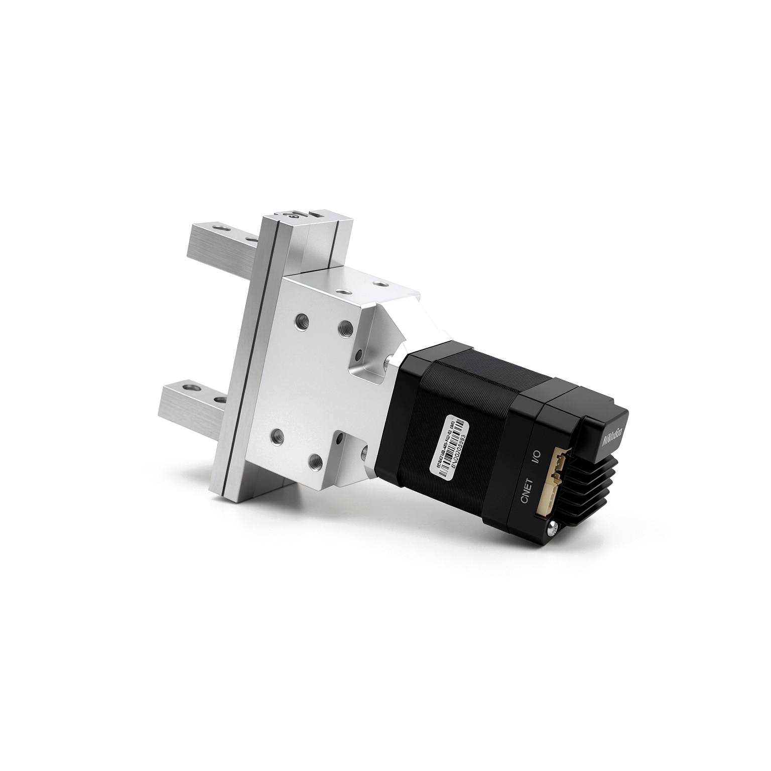
Protection reminder: the IP20 rating means the NGM20L targets standard workshop environments and does not resist splash or dust. For machining-center coolant environments or outdoor use, add a protective cover or choose a higher protection class.
5. Selection advice: when to pick the NGM20L
Combining the specifications with product-line positioning, here are three actionable selection rules:
Grip force 40–150N, space for a 42mm base: the NGM20L is currently the only mid-load screw-driven tier in the line, saving the selection and integration cost of a DIY "motor + screw + drive" build.
Cycle time first, very light load (≤10N): choose the NGM18 or the servo NPGM18 — open/close in 0.1–0.13s, about 4× faster than the NGM20L's 0.5s.
Small workpieces, torque gripping, or full CiA402 mode control (CSP/CSV/CST etc.): the NGM12L supports CiA402's PP/VM/PV/PT/HM/IP/CSP/CSV/CST modes with higher control flexibility; the NGM20L covers mainstream scenarios with PIO/single/loop modes and simpler configuration.
An objective note: the NGM20L is a stepper-servo solution with strong static holding torque, good low-speed force characteristics, and lower cost than an equivalent servo. But if your application demands dynamic stiffness at very high cycle rates and full closed-loop force curves, still evaluate servo products like the NPGM. The selection logic is to fix grip force and cycle time first, then drive mechanism and control mode — not the other way around.
6. FAQ
Q1: How heavy a workpiece can the NGM20L's 150N grip force handle?
A: The 150N is the rated normal force at the jaws; payload depends on friction coefficient, jaw length, and acceleration. For metal parts with a friction coefficient of 0.1–0.2 and a reasonable safety factor (typically 3–5×), it suits reliable handling of parts from several hundred grams up to about 1kg. Calculate per workpiece shape and acceleration, and refer to the load torque limits in the manual (MX 6N·m / MY 3N·m / MZ 3N·m).
Q2: NGM20L or NGM12L — which one?
A: The core differences are grip force and control modes. The NGM12L is rated 40N with a 28mm base and full CiA402 servo modes; the NGM20L is rated 150N with a 42mm base and PIO/single/loop execution modes. Light loads with complex control → NGM12L. Heavy loads with simpler wiring and setup → NGM20L.
Q3: Is it complicated to switch from a pneumatic gripper to the NGM20L?
A: Not really. The PIO mode is designed for exactly this retrofit: the 3 NPN inputs can be triggered directly by the original PLC's switching outputs to fire preset open/close actions. Power is 24VDC (16–30VDC wide range) — connect the old solenoid valve wires to the DI terminals and the basic retrofit is done, with adjustable grip position/speed and power-loss position memory as a bonus.
Q4: Is the gripper position lost after a power outage?
A: No. The NGM20L has a 17-bit single-turn absolute magnetic encoder with multi-turn counting and automatic power-loss storage — no re-homing after power-up. Note that the IP20 body does not provide mechanical self-locking that keeps grip during power loss; evaluate a holding solution where drop prevention is required.
Q5: Which host systems and commissioning tools are supported?
A: The RS485 version runs Modbus RTU (NiMotion protocol compatible) and the CANopen version runs standard CANopen, connecting to mainstream PLCs and motion controllers. The product supports fault diagnosis/reset, parameter identification, gain switching, and online upgrade; see the product manual (LMS-C12-26059) for register and object dictionary definitions.