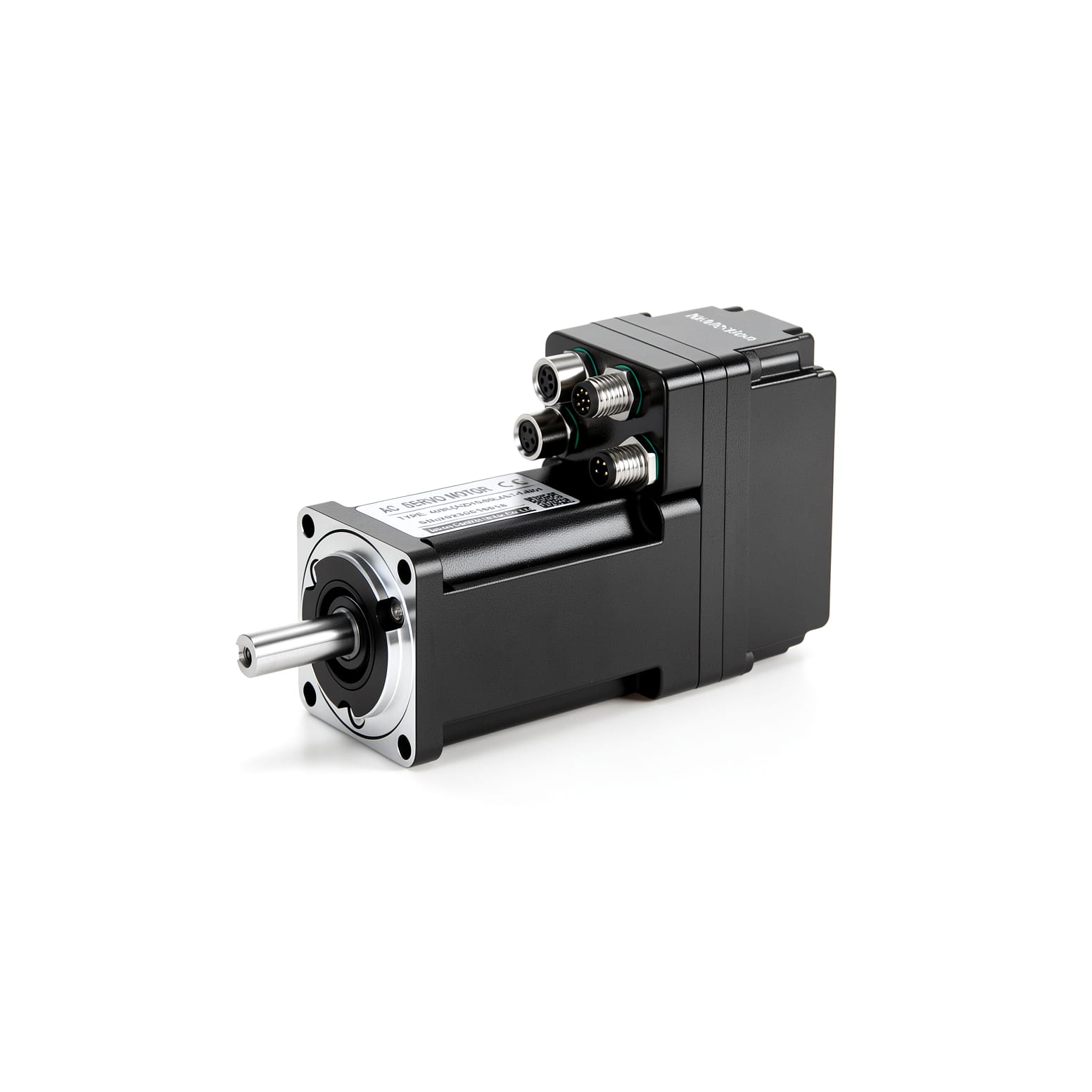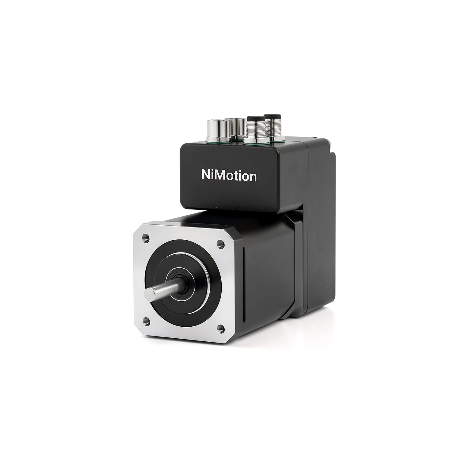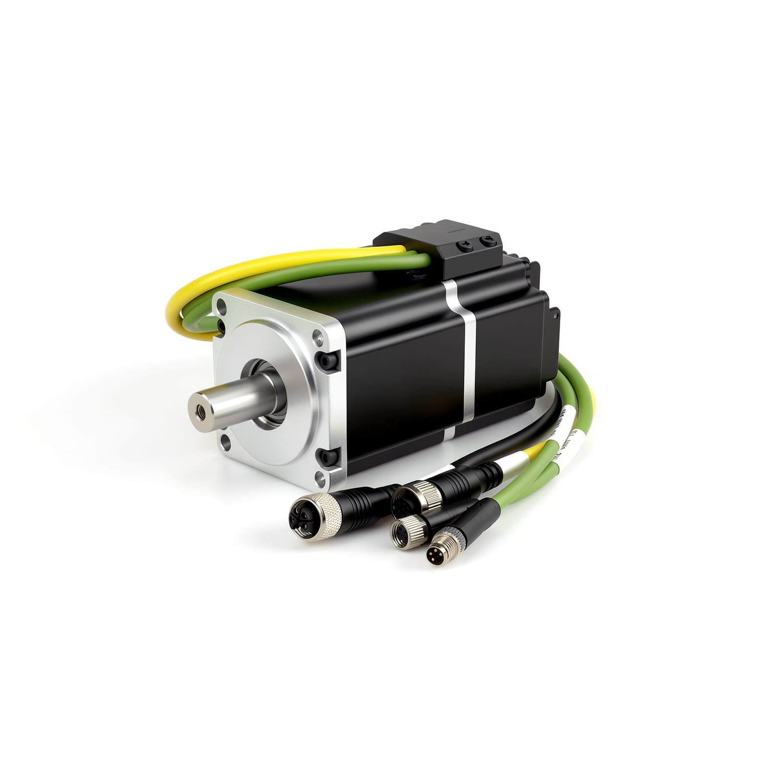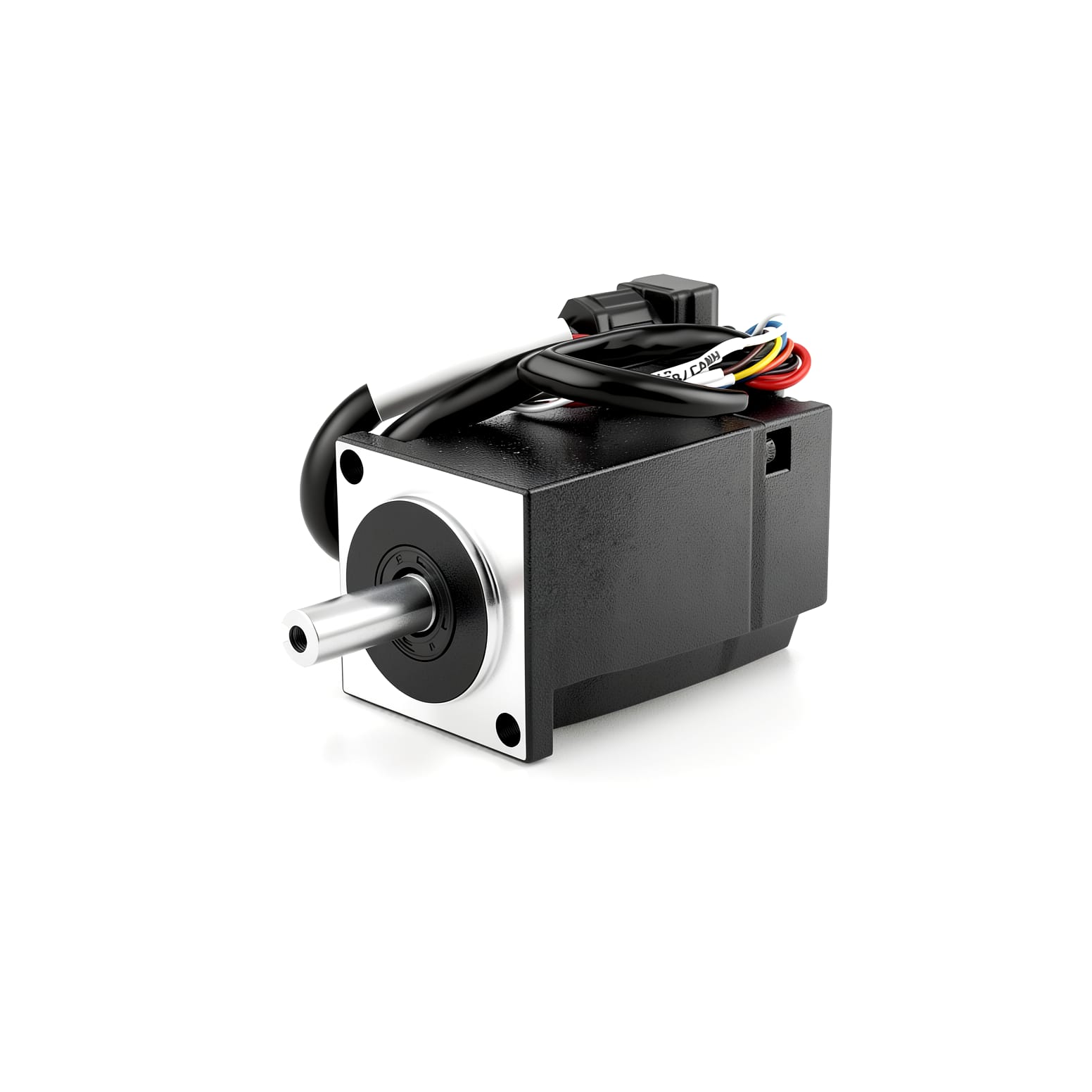
NiMotion Releases the STMP57M-CCR Waterproof Integrated Stepper Servo Motor: IP65 Protection + Rear Cable Exit + 48V Wide Voltage
NiMotion has released the STMP57M-CCR series waterproof integrated stepper servo motor — combining IP65 protection, 16–72VDC wide-voltage supply (48V rated), and a 17-bit single-turn absolute encoder in a 57mm frame, with one bus type per model (CANopen or RS485) and two torque options of 1.1N·m and 1.8N·m. Its headline feature is the rear cable exit — cables now leave axially from the tail of the body instead of the front, ending the fight for space in tight installations.
I. Product Positioning: Introducing a Rear-Exit Cable Design to the Protected Series (Size 57)
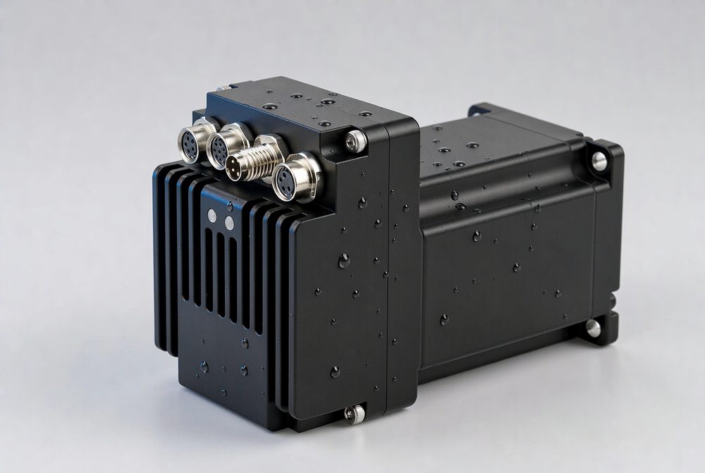
Among the challenges in stepper motor applications, "environmental factors" rank second only to "step loss." In sectors such as food packaging, medical devices, external machine tool components, and outdoor equipment—environments characterized by moisture, dust, or the need for frequent washdowns—standard IP20 integrated motors often suffer from reduced service life and compromised reliability.
NiMotion’s integrated stepper motor product line is clearly segmented: the STM standard series (IP20; frame sizes 28/42/57/86) covers conventional applications; the STMP protected series (IP65) is designed for harsh environments; and the STMPW wide-temperature series extends the operational temperature range. The STMP57M-CCR upgrades the size 57 model within the protected series, featuring an IP65 rating, a wide voltage range (16–72V), and a 17-bit absolute encoder. However, its most notable feature is the rear-exit cable design.
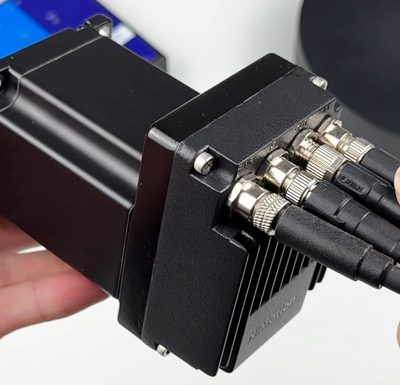
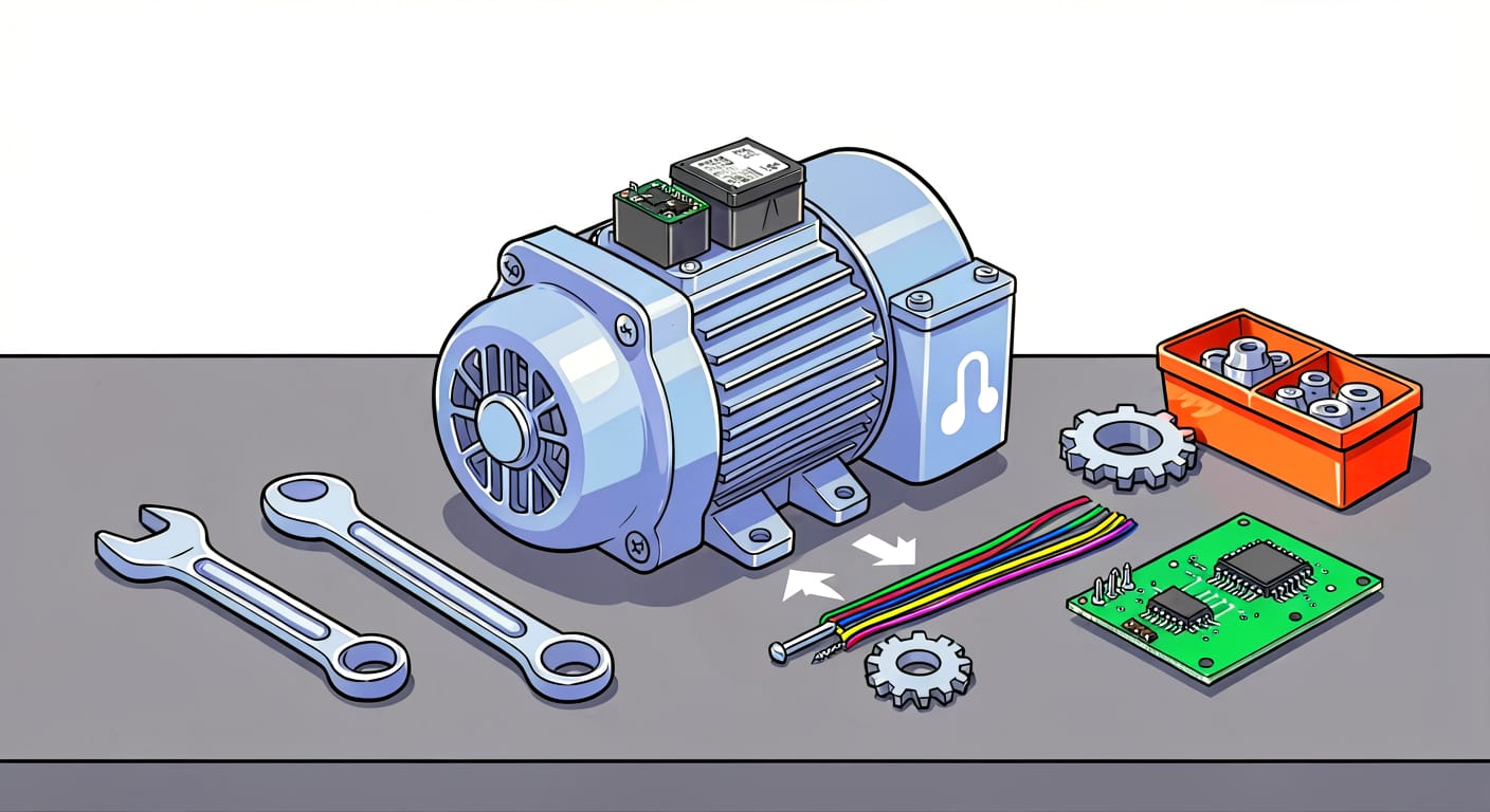
Why is the rear-exit cable design so significant? Most integrated motors traditionally feature a front-exit design, where cables emerge near the shaft extension. When such a motor is mounted flush against a wall or recessed into a bracket, the cable exit often faces the mounting surface, forcing the cable to make a sharp, awkward bend. This consumes extra lateral space and increases the risk of cable abrasion or damage to the connectors. The STMP57M-CCR shifts the cable exit to the rear of the motor housing (opposite the shaft extension):
· Unobstructed axial routing: When the motor is mounted flush or recessed, the cable extends directly backward, eliminating interference with the mounting surface.
· Tidier multi-unit installations: With cables exiting in the same direction along a single axis, the wiring remains organized and less prone to tangling.
· Enhanced connector safety: By positioning the cable exit away from the active work area and moving parts, the risk of poor contact caused by accidental impacts or pulling is significantly reduced. For applications such as food packaging and medical equipment—where frequent washdowns occur and space for cabling is limited—this design change translates into tangible savings in installation time and reduced maintenance headaches.
The product name reveals its configuration: "STM" denotes an integrated stepper motor; "P" indicates an IP65 protection rating; "57" refers to the 57mm frame size; "B" signifies a 17-bit single-turn absolute encoder; and the interface is either CANopen or RS485 (depending on the specific model). Two body lengths—56mm and 76mm—are available, corresponding to different torque ratings. The "-CCR" suffix is a hardware feature code, indicating a version with a rear-facing cable exit.
Shaft configurations include options for a plain shaft, a D-cut (milled flat) shaft, a semi-circular key, a standard parallel key, or a through-hole mounting design. Additionally, custom shaft lengths and specialized gear machining are available—offering valuable flexibility for engineers selecting components for non-standard equipment.
II. Integrated Architecture: Drive Electronics Housed Within the Motor, Freeing Up Space in the Electrical Cabinet
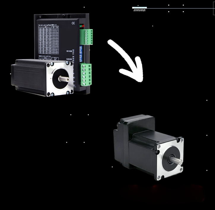
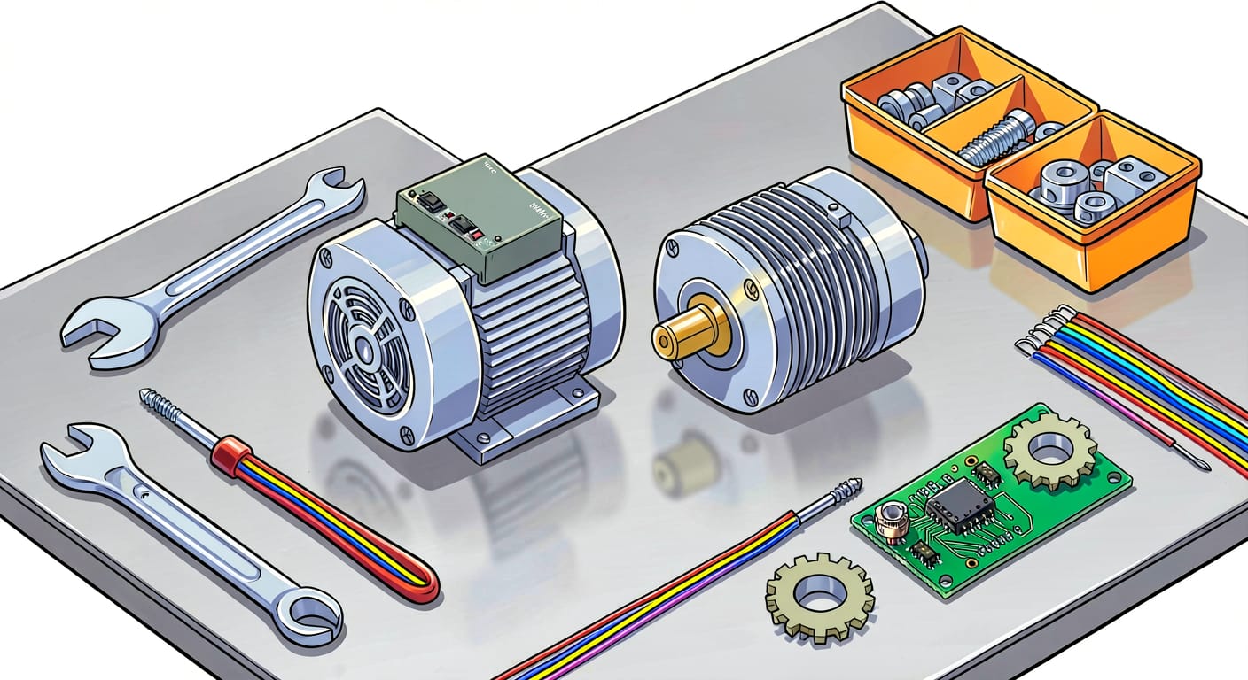
The STMP57M-CCR continues the "integrated drive and control" philosophy: the stepper motor, FOC (Field-Oriented Control) driver, encoder, controller, and I/O interfaces are all housed within a 57mm-frame body. For equipment engineers, this offers three key advantages:
· Eliminates the need for a standalone driver: This saves installation space, allowing for significantly smaller electrical cabinets—or even the complete elimination of the cabinet—in multi-axis systems.
· Simplified cabling: Only two connections are required—a power supply and a single bus cable (CANopen or RS485, depending on the model). Combined with the rear-facing cable exit, internal machine wiring is greatly streamlined.
· Factory-tuned performance: FOC and SVPWM (Space Vector Pulse Width Modulation) parameters are pre-configured at the factory, eliminating the need for on-site current-loop tuning.
The encoder specification is particularly noteworthy: it features a 17-bit single-turn absolute encoder. Unlike incremental encoders, an absolute encoder can determine its position within a single rotation immediately upon power-up—without requiring a "homing" or "return-to-zero" sequence. This provides a significant practical benefit for production lines that undergo frequent washdowns or require frequent start-stop cycles.
III. Communication and Control: Bus Selection by Model + Comprehensive I/O
The STMP57M-CCR series is available in CANopen and RS485 versions, with each model corresponding to a specific communication bus. Users should select the appropriate version based on the protocol used by their host controller:
· CANopen Version: Supports CAN 2.0A with nine selectable baud rates (1 Mbps, 800k, 500k, 250k, 125k, 100k, 50k, 20k, and 10 kbps) and features a built-in 120Ω terminal resistor.
· RS485 Version: Utilizes the Modbus-RTU protocol (compatible with the NiMotion protocol). It supports a wide range of common baud rates—such as 9.6k, 19.2k, 38.4k, 57.6k, 115.2k, 230.4k, 460.8k, and 921.6k—and complies with the EN50 170 and GB/T 19582.2-2008 standards (please refer to the user manual for the full range of supported specifications).
Both versions feature a dual-port (IN/OUT) design, enabling plug-and-play connectivity for multi-unit configurations via a clear daisy-chain topology.
The I/O configuration is tailored for standard production line control, including 3 digital inputs (DI1/DI2/DI3; supports NPN/PNP wiring), 1 analog input (-10V to +10V), and 1 digital output (DO1). This setup covers essential closed-loop control functions, such as start/stop commands, homing triggers, and status feedback. A comprehensive supporting ecosystem is also available: the manufacturer offers pre-assembled VDDX/VDCX series cables (for power and bus connections) along with USBCANI-L-LP / USB485A-L-LP USB debugging converters. These allow for parameter configuration and online firmware upgrades simply by connecting to a PC—eliminating the need for manual wire stripping or crimping terminals.
IV. Quick Overview of Key Parameters (STMP5756B-CCR / STMP5776B-CCR)
Project | STMP5756B-CCR | STMP5776B-CCR |
Base width | 57mm | 57mm |
Protection Rating | IP65 | IP65 |
Qualification Path | Rear cable exit (routed axially from the rear of the unit) | Same as on the left |
Supply voltage | 16~72VDC(Rated 48VDC) | Same as on the left |
Rated current | 5A | 5A |
Rated torque | 1.1N·m | 1.8N·m |
Encoder | 17-bit single-turn absolute value | Same as on the left |
Total fuselage length | 82mm | 103mm |
weight | 0.82kg | 1.15kg |
Control Technology | FOC + SVPWM | Same as on the left |
communication | CANopen or RS485(Choose one based on the model) | Same as on the left |
I/O | 3×DI + 1×AI + 1×DO | Same as on the left |
Work Environment | 0~40℃,10%–85% RH, non-condensing; altitude < 1000 m | Same as on the left |
Storage temperature | -40~85℃ | Same as on the left |
Please note: While the unit carries an IP65 rating—offering protection against water jets and dust—direct exposure to high-pressure water jets (such as those from a pressure washer) on the motor body or cable exit point is not recommended. If your operating environment requires high-pressure washdown (IP69K standard), please consult the manufacturer or implement additional protective measures. The 48V specification represents the rated voltage for the torque curve; if the actual supply voltage falls below 48V, both torque and rotational speed will decrease according to the corresponding performance curves. The wide operating voltage range of 16–72VDC provides flexibility in integration, but it does not imply that full torque is maintained regardless of the input voltage.
V. Selection Guide: When to Choose the STMP57M-CCR
Based on the product specifications and its position within the product line, here are three criteria for selection:
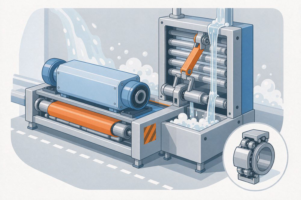
· For waterproof applications with limited axial installation space or restricted cable routing: The combination of a rear-exit cable and an IP65 rating is specifically designed for such environments. This configuration—where the rear of the motor is recessed and the cable exits axially—is ideal for applications in food packaging, medical device cleaning, or outdoor shaft-driven systems.
· For torque requirements between 1.1 N·m and 1.8 N·m: Choose between the 56-series (1.1 N·m, 82 mm, 0.82 kg) and the 76-series (1.8 N·m, 103 mm, 1.15 kg) based on your available space and load requirements. In most cases, the additional 21 mm of length in the 76-series is a worthwhile trade-off for a 63% increase in torque.
· For torque requirements exceeding 2 N·m or applications demanding high-performance closed-loop control: Consider the STM57-M/ME series (standard stepper-servo) or the PMM series (integrated servo). For standard environments where high ingress protection is not required, the IP20-rated STM57 standard model offers a more cost-effective solution. Objective assessment: Stepper-servo systems are more cost-effective than DC servo systems of equivalent specifications and offer superior torque characteristics at low speeds; however, they exhibit weaker dynamic response at high speeds and lower short-term overload capacity. When selecting a system, the correct approach is to first determine the required environmental protection rating and torque, followed by the bus interface and encoder configuration—never the other way around.