
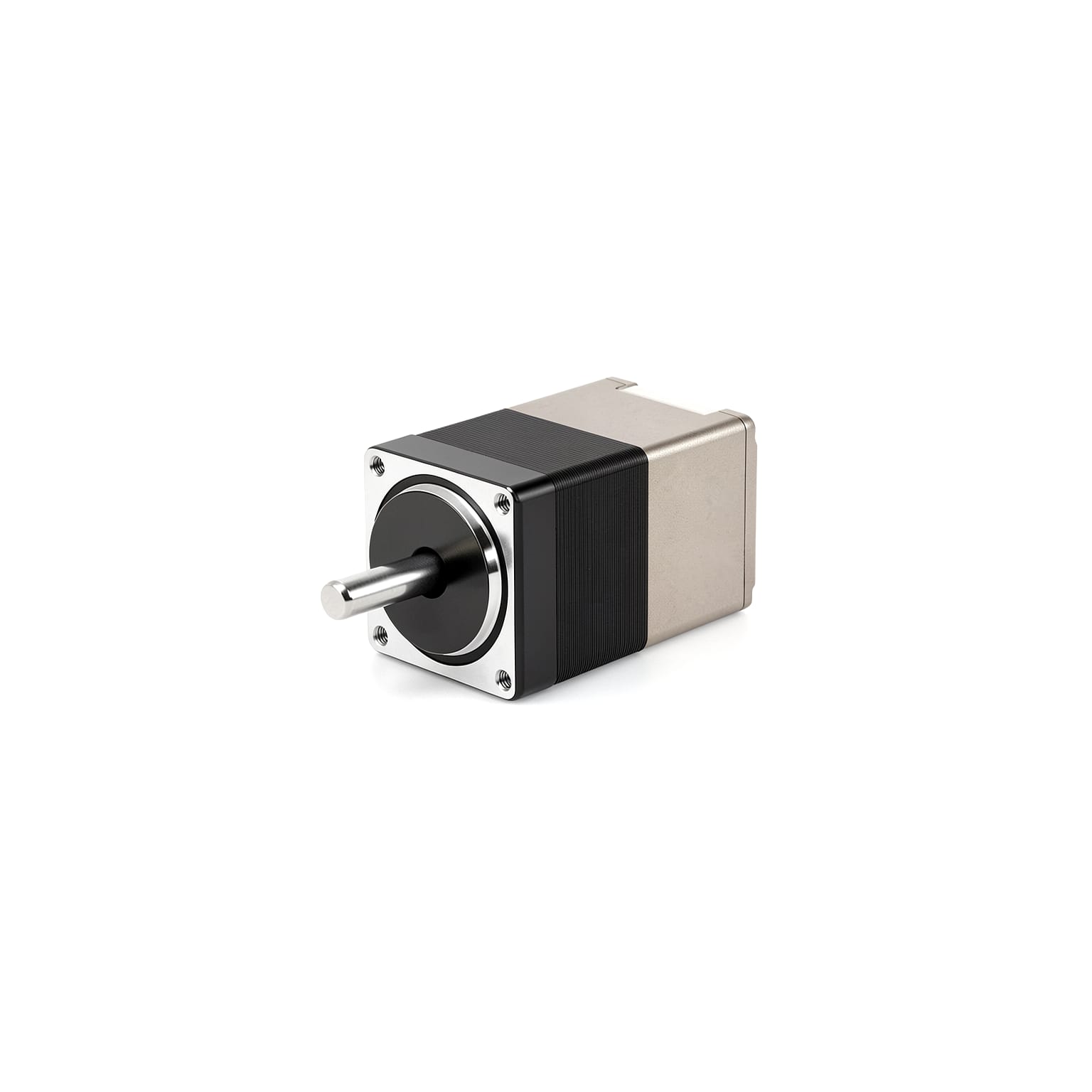
STM28 (Open-Loop) Integrated Stepper Motor
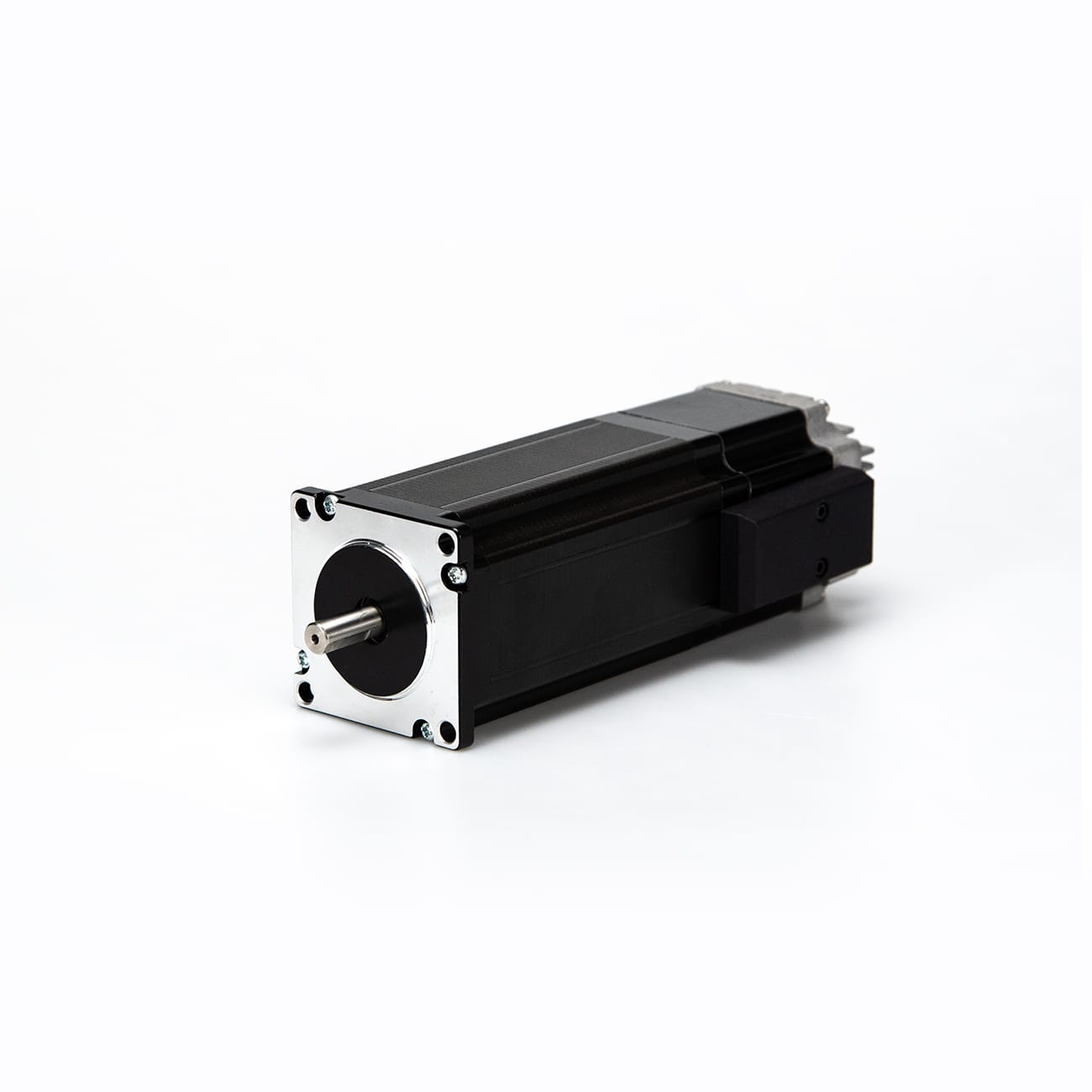
Compact integrated stepper motor, redefining traditional distributed solutions by seamlessly combining stepper motor, driver, controller, and I/O interfaces into a single unit. Minimizes wiring, reduces failure points, and empowers a wide range of precision compact automation applications with smarter and more reliable performance.
Features
- CAN/CANopen/RS485
- 14-bit encoder for closed-loop
- Supports DI and DO Control
Models & Specifications
| Specifications | STM2832-CAN-0FS | STM2832-CANopen-0FS | STM2832-485-0FS | STM2851-CAN-0FS | STM2851-CANopen-0FS | STM2851-485-0FS |
|---|---|---|---|---|---|---|
| Flange Size | 28mm | 28mm | 28mm | 28mm | 28mm | 28mm |
| Brake | No Brake | No Brake | No Brake | No Brake | No Brake | No Brake |
| Open-Loop/Closed-Loop | Open-loop | Open-loop | Open-loop | Open-loop | Open-loop | Open-loop |
| Encoder Type | No Encoder | No Encoder | No Encoder | No Encoder | No Encoder | No Encoder |
| Rated Voltage | 24 VDC | 24 VDC | 24 VDC | 24 VDC | 24 VDC | 24 VDC |
| Voltage Range | 12-30VDC | 12-30VDC | 12-30VDC | 12-30VDC | 12-30VDC | 12-30VDC |
| Rated Current | 1.0 A | 1.0 A | 1.0 A | 1.0 A | 1.0 A | 1.0 A |
| Inertia | - | - | - | - | - | - |
| Body Length | 47 mm | 47 mm | 47 mm | 65.5 mm | 65.5 mm | 65.5 mm |
| Weight | 0.11 kg | 0.11 kg | 0.11 kg | 0.20 kg | 0.20 kg | 0.20 kg |
* Scroll horizontally within the table area when the content is wide.
Specifications
| Shaft Diameter | Φ5 |
| Number Of Phases | 2 |
| Step Angle | 1.8° |
| Encoder Introduction | No encoder |
| Subdivision | 1,2,4,8,16 |
| Control Modes | CiA402 Mode,Manufacturer Mode,Position Mode,Velocity Mode,Homing Mode |
| External Control Interface | DI – Non-isolated NPN Input,DI – Non-isolated Switch Input,DO – Isolated Open-Drain Output,DO – Non-isolated MOSFET Output |
| CiA402 Mode | PP, VM, PV, HM, IP, CSP, CSV (via CANopen communication) |
| DI (Digital Input) | Quantity 3; Not isolated; Level input, passive contact input. Logic 1 signal: 5~24V. Logical 0 signal: 0~2V |
| DO (Digital Output) | Quantity 2; Output mode: MOS open leakage output, DO load maximum current 100mA, maximum voltage 30V |
| DX (Digital Input / Output) | - |
| AI (Analog Input) | - |
| Operating Temperature | 0°C to 40°C |
| Operating Altitude | <1000m |
| Fault Alarm | Overvoltage, undervoltage, overheat, locked rotor |
Torque-Speed Characteristics
STM2832A-CAN/485-XX
STM2851A-CAN/485-XX
Product Details
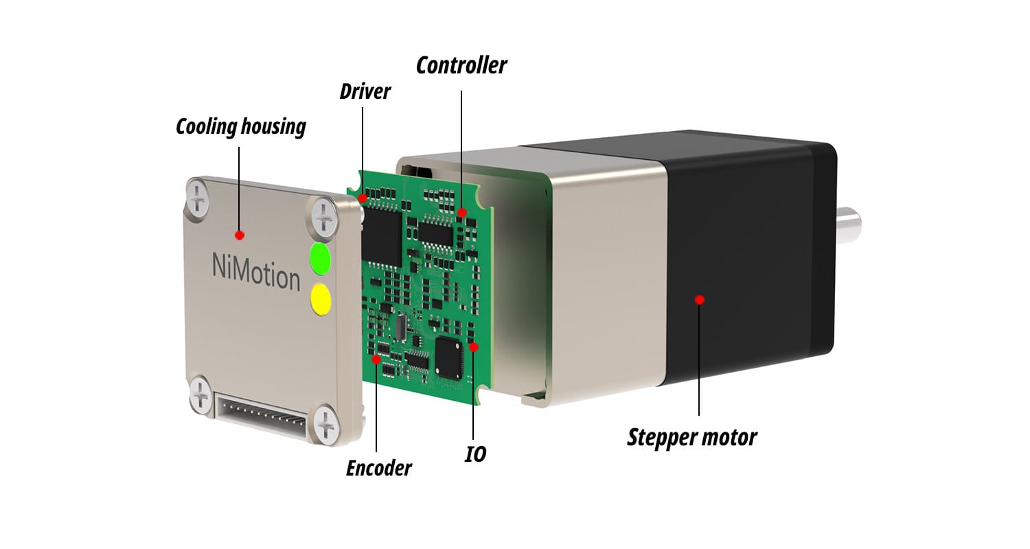
The STM28 series integrated stepper motor is a step product independently developed by NiMotion. With its excellent closed-loop control system and integrated development concept, the stepper motor, encoder, driver and digital IO are integrated into one. Support can, CANopen, RS485 communication bus control, small size, simple wiring.
Product Features
Highly integrated design
All-in-one design deeply integrating the motor body with the drive and encoder, giving a compact body, simple wiring and easier machine integration.
High Precision Encoder Feedback
Built-in 14-bit high-resolution absolute encoder (closed-loop support) provides real-time position and speed feedback for more accurate closed-loop control, ensuring smoother operation and more accurate positioning.
Multi-bus communication support
Supports CANopen and RS485 communication, allowing quick connection to mainstream PLCs, motion controllers and host systems, with flexible networking and easy expansion.
Standard CiA 402 Sport Mode
Supports CiA 402 standard motion modes (PP, PV, HM, CSP, CSV, etc.) as well as position mode, velocity mode and homing mode, ensuring compatibility with mainstream fieldbus motion-control architectures and making replacement and commissioning easier.
Wide Voltage Input
Wide input voltage range of 12 -30VDC, suitable for various power-supply environments and giving greater flexibility in system integration and retrofitting.
Segment can be set
Micro-stepping setting of 1、2、4、8、16 steps selectable effectively reduces low-speed vibration and noise and improves positioning resolution and smoothness.
Overall Dimensions
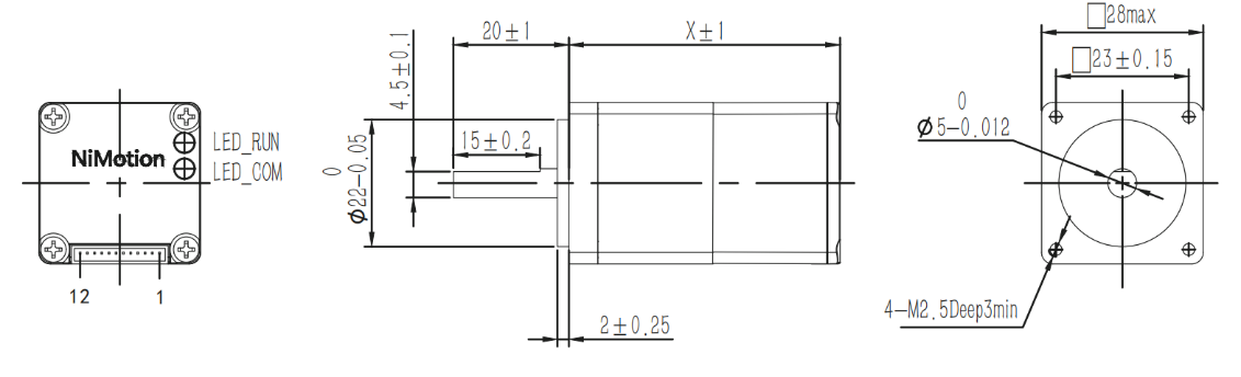
Base width: 28mm, X represents the body length. Please click the "Download" section below to view detailed drawings.
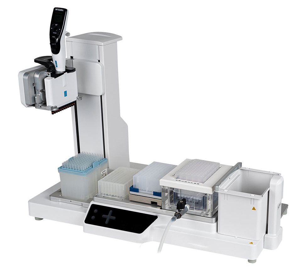
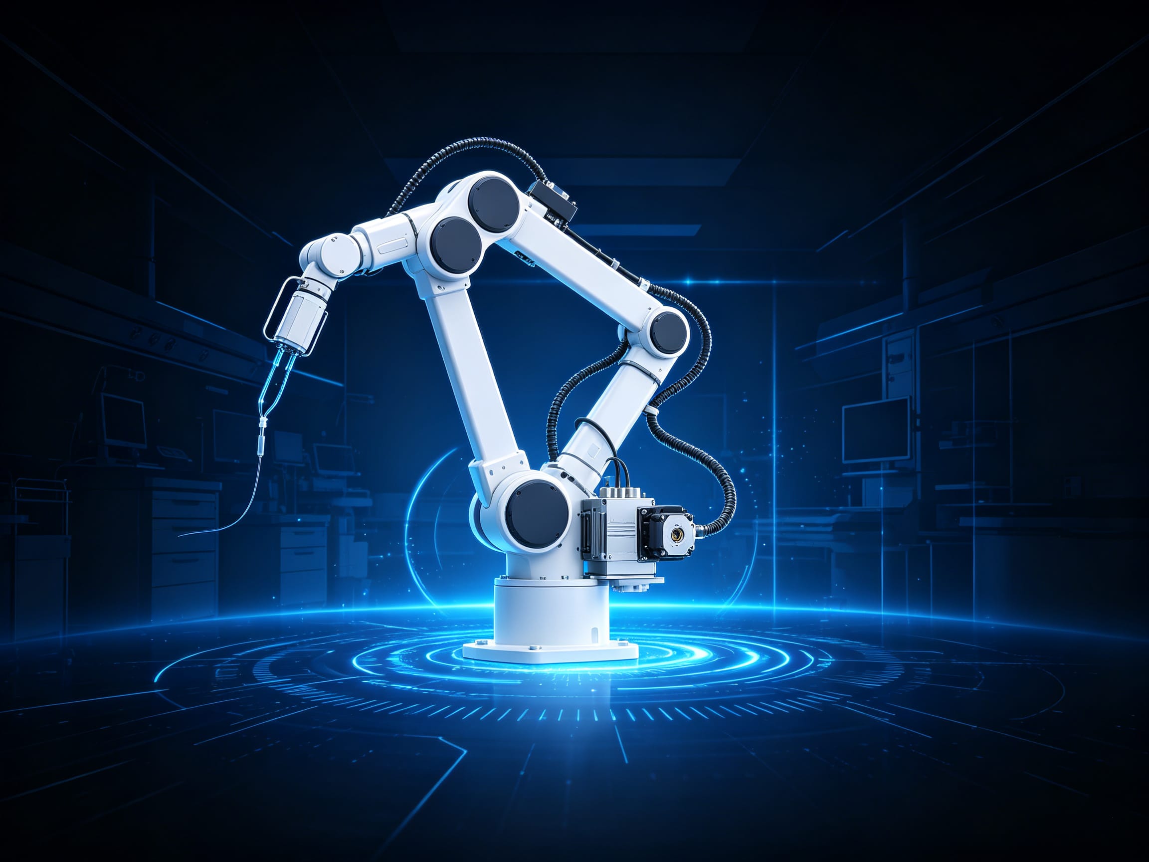
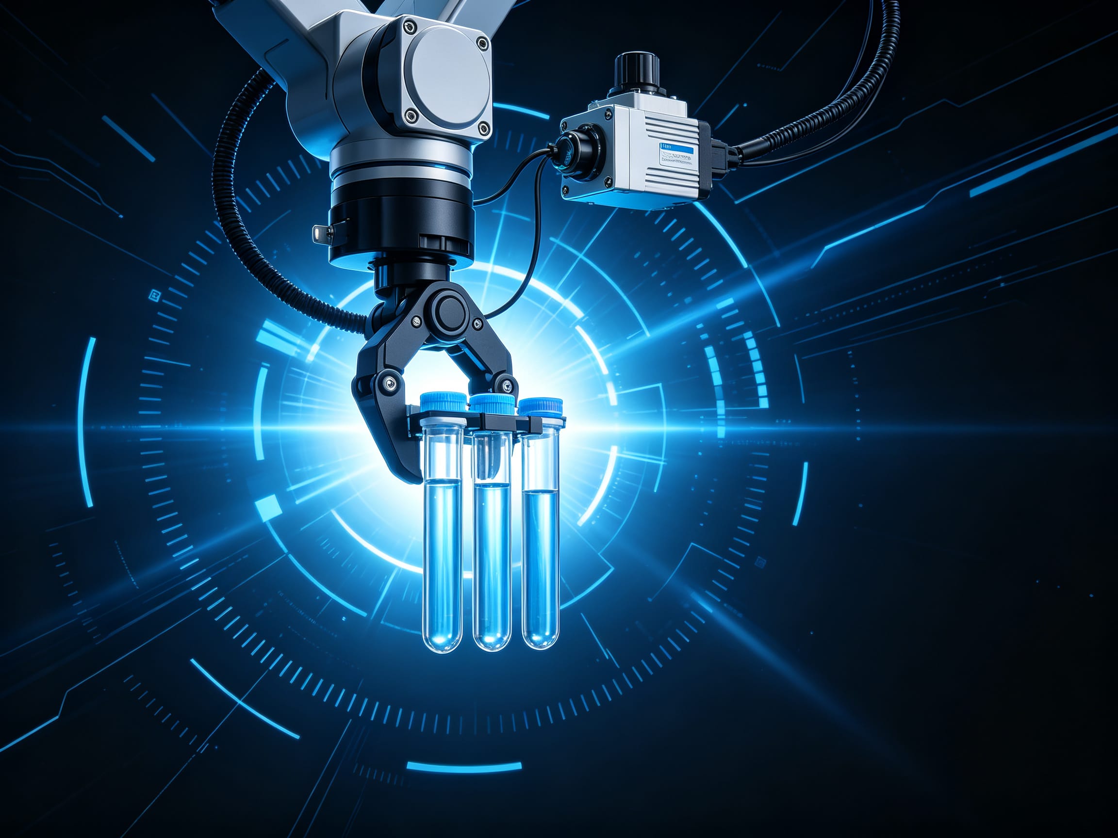
Application in Fully Automatic Pipetting Equipment
The STM28 features a compact size, closed-loop control with no step loss, and a built-in driver. Its core advantages lie in its integrated design and precision control capabilities: the compact form factor supports high-density side-by-side mounting, significantly saving equipment space. The built-in closed-loop encoder, combined with vector drive, delivers absolute positioning and real-time torque compensation, effectively minimizing errors caused by liquid load fluctuations. The highly integrated design simplifies external wiring and driver requirements, reducing system assembly complexity.
Downloads
Companion Products
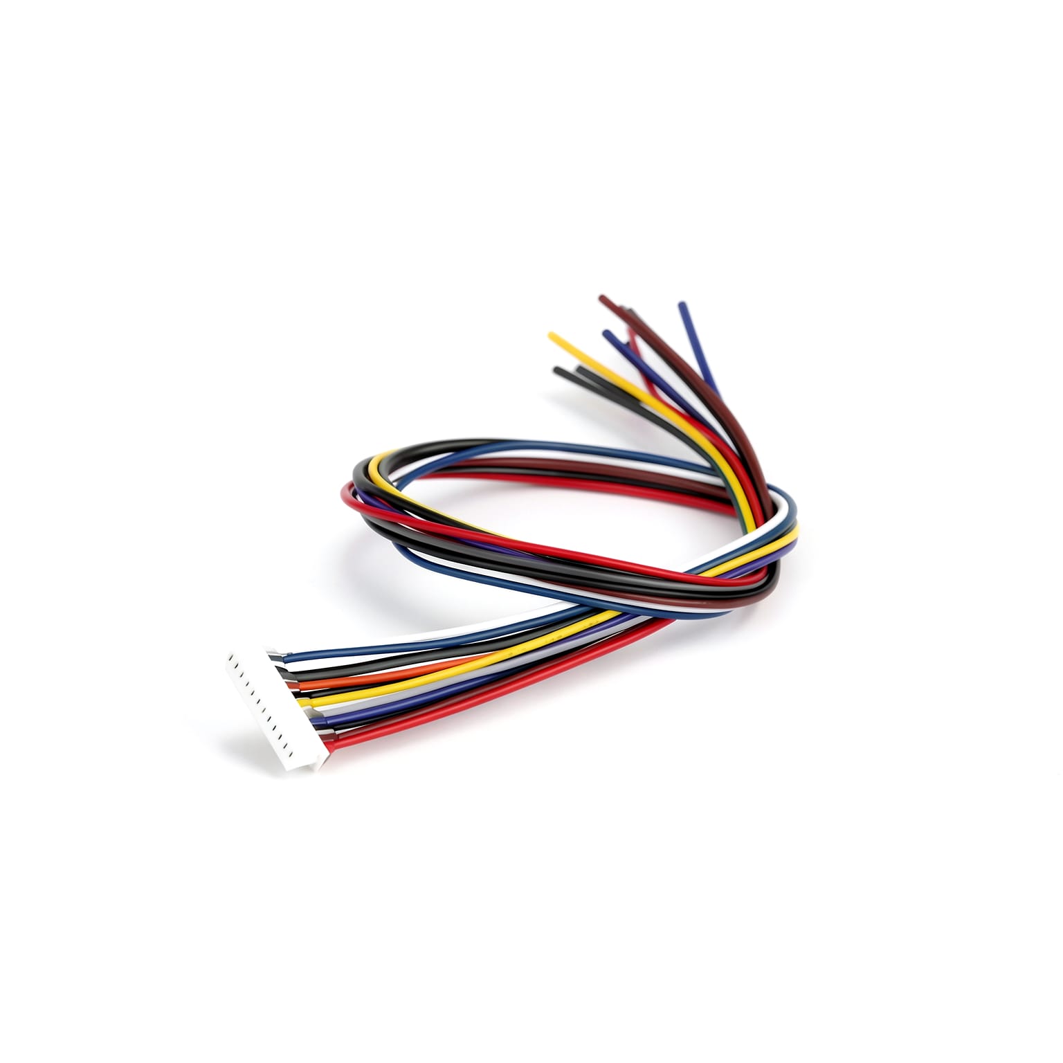
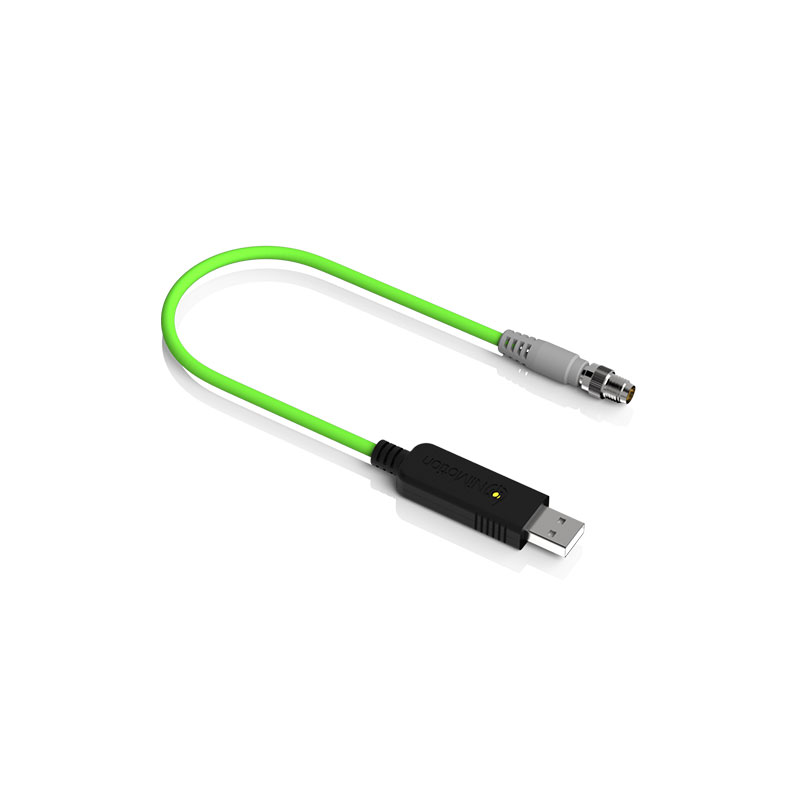
USB to CAN converter with isolation, IP65 protection, and secondary development SDK support.
USB to RS485 converter with active termination, isolation, IP65 protection, and secondary development SDK support.
FAQ
2‑phase motors are less expensive but exhibit more vibration at low speeds and have a steeper torque drop at high speeds. 5‑phase motors have lower vibration and better high‑speed performance – they can run 30‑50% faster than 2‑phase motors, and can replace servo motors in some applications. For general cost‑sensitive uses, choose 2‑phase; if vibration and high‑speed performance are critical, choose 5‑phase.
Microstepping is essentially an electronic damping technique, primarily designed to reduce or eliminate low‑frequency vibration. Improved positional resolution is a secondary benefit. Different manufacturers’ microstepping drivers can vary greatly in accuracy, and higher microstepping numbers are harder to control precisely.
This is due to the motor’s pull‑in rate – the maximum pulse frequency at which it can start from standstill without losing steps. If the pulse frequency exceeds this rate, the motor cannot start properly and may lose steps or stall. The solution is to use an acceleration ramp: start at a low frequency and gradually increase to the target high frequency. Integrated stepper motors allow you to set acceleration and deceleration parameters freely.
When the motor rotates, the inductance in each phase winding generates a back‑EMF. The higher the frequency, the greater the back‑EMF, which reduces the phase current and thus lowers the torque.
Excessive temperature can demagnetise the magnetic material, reducing torque and causing step loss. The demagnetisation point is generally above 130°C, some up to 200°C. Therefore, a surface temperature of 80‑90°C is perfectly normal for a stepper motor. The most common insulation class is Class B, with a rated operating temperature up to 130°C.
Applications
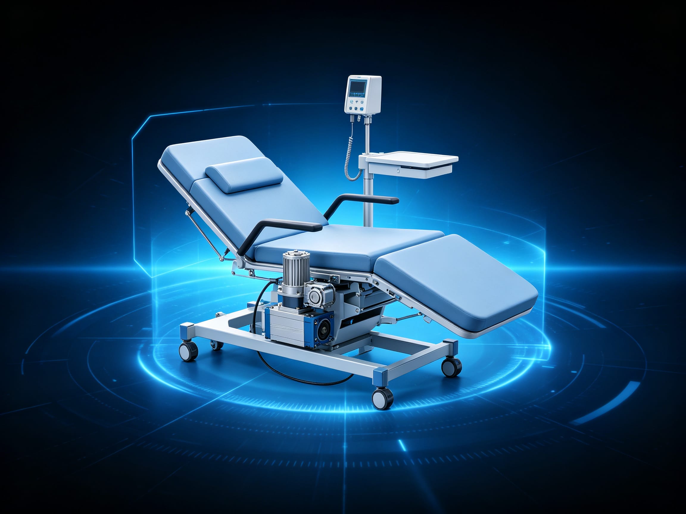
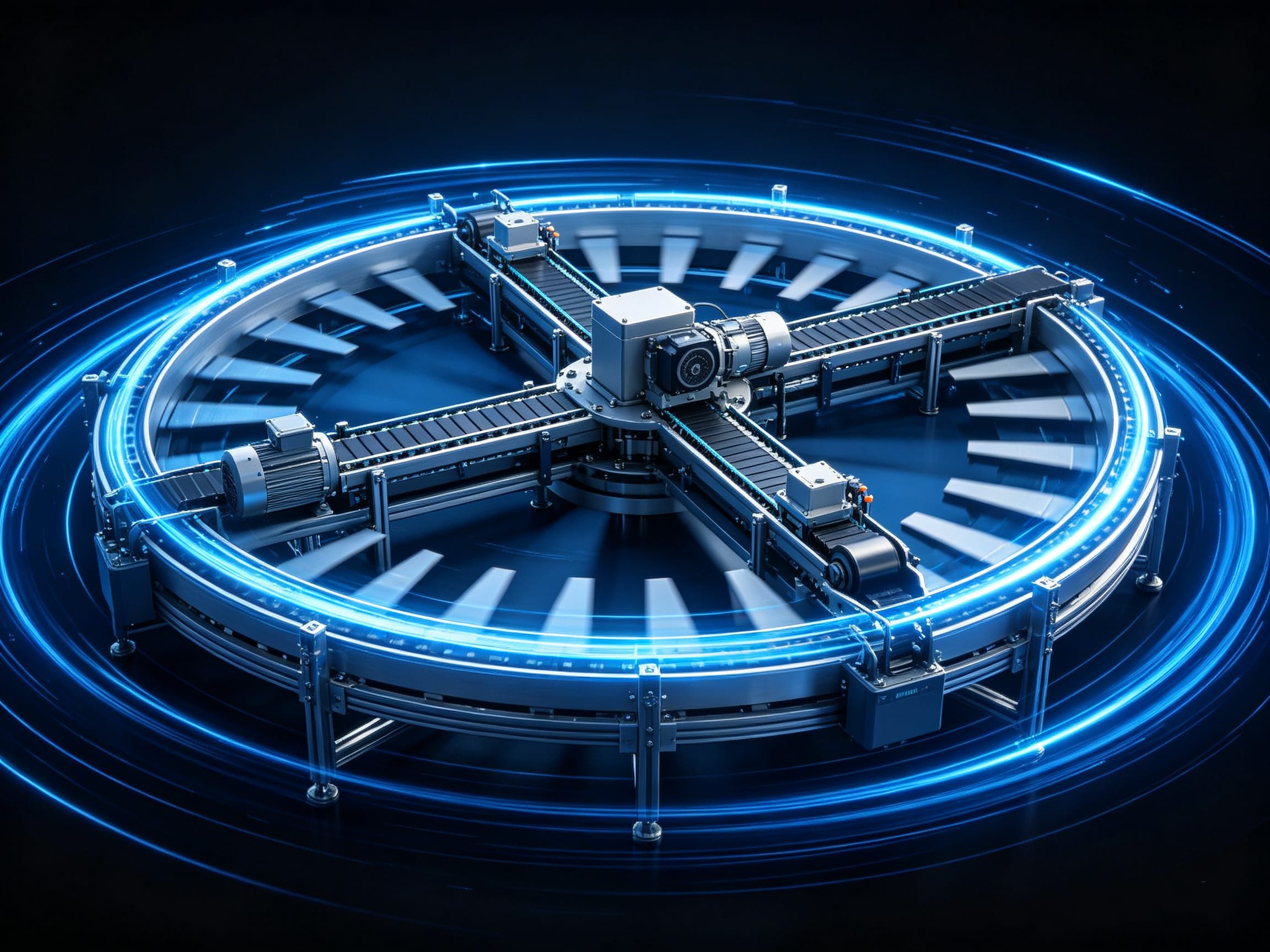
Discover how this product is applied across various industrial automation scenarios.

Compatible Products
Build complete and reliable solutions with our compatible products.
Technical Resources
Technical guides, application notes, and more to help you get the most out of the product.
Ready to start your automation project?
Talk to our engineers and get a customized motion control solution within 24 hours.
Typical response time: 24 hours