
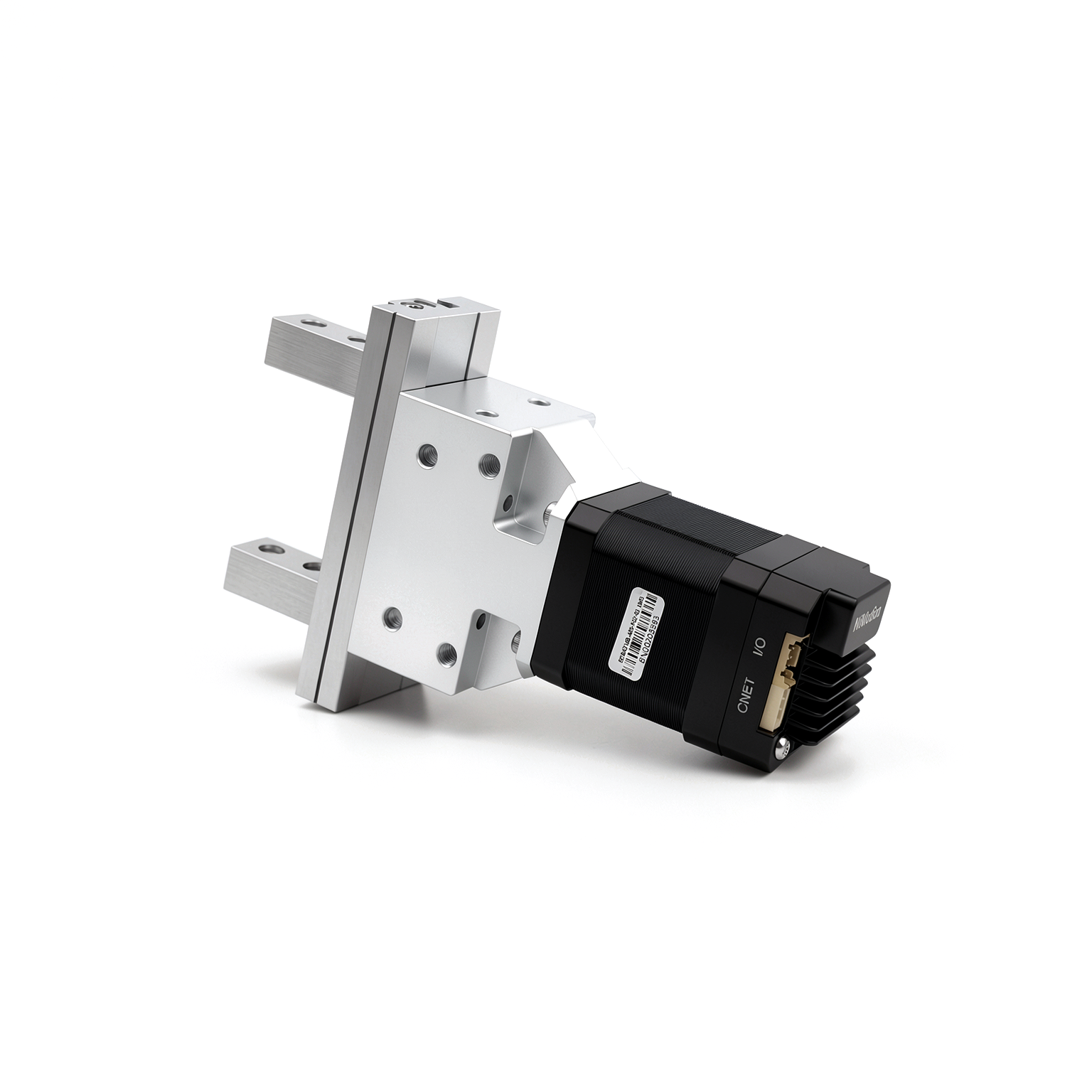
NGM12 Series Compact Electric Gripper
Compact electric gripper with STM42M stepper servo, supports MODBUS RTU or CANopen.
Features
- Small footprint
- High clamping force (150N)
- Lead screw transmission
- Bus control
Models & Specifications
| Specifications | NGM20F0 |
|---|---|
| Communication Method | CANopen、RS485 |
| Total Stroke | 20mm |
| Gripping Force | 150N |
| Rated Voltage | 24V |
| Rated Current | 1A |
| Body Length | 160×97.4×42.3mm |
* Scroll horizontally within the table area when the content is wide.
Specifications
| Unidirectional Stroke Time | 0.5s |
| Repeat Positioning Accuracy | - |
| Backlash | - |
| Transmission Mode | Lead screw + gripper jaws |
| Gripper Allowable Load Torque | MX:6Nm, MY:3Nm, MZ:3Nm |
| Input Power Voltage Range | 16-30V |
| Operating Temperature | 0℃~40℃ |
| Operating Altitude | <1000m |
| Special Features | Fault diagnosis, fault reset, soft limit, parameter identification, online upgrade |
| DI (Digital Input) | Quantity: 3; NPN input; Logic 1 signal: 5–24VDC input; Logic 0 signal: 0–2VDC input; Configurable function: Can be used as motion control signals. |
| DO (Digital Output) | Quantity: 1; Output method: open-drain output; Maximum current: 100mA; Maximum voltage: 30VDC; Configurable functions: 1. General DO port; 2. Motor run/stop; 3. Target reached; 4. Alarm output (when the motor status meets the above conditions, the DO switching state changes). |
Product Details
Downloads
Companion Products
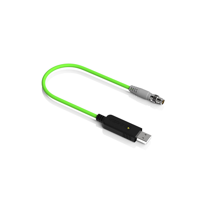
USB to CAN converter with isolation, IP65 protection, and secondary development SDK support.
USB to RS485 converter with active termination, isolation, IP65 protection, and secondary development SDK support.
FAQ
The positional accuracy of a stepper motor is about 3‑5% of the step angle, and it does not accumulate errors.
Microstepping is essentially an electronic damping technique, primarily designed to reduce or eliminate low‑frequency vibration. Improved positional resolution is a secondary benefit. Different manufacturers’ microstepping drivers can vary greatly in accuracy, and higher microstepping numbers are harder to control precisely.
This is due to the motor’s pull‑in rate – the maximum pulse frequency at which it can start from standstill without losing steps. If the pulse frequency exceeds this rate, the motor cannot start properly and may lose steps or stall. The solution is to use an acceleration ramp: start at a low frequency and gradually increase to the target high frequency. Integrated stepper motors allow you to set acceleration and deceleration parameters freely.
When the motor rotates, the inductance in each phase winding generates a back‑EMF. The higher the frequency, the greater the back‑EMF, which reduces the phase current and thus lowers the torque.
Excessive temperature can demagnetise the magnetic material, reducing torque and causing step loss. The demagnetisation point is generally above 130°C, some up to 200°C. Therefore, a surface temperature of 80‑90°C is perfectly normal for a stepper motor. The most common insulation class is Class B, with a rated operating temperature up to 130°C.
Applications
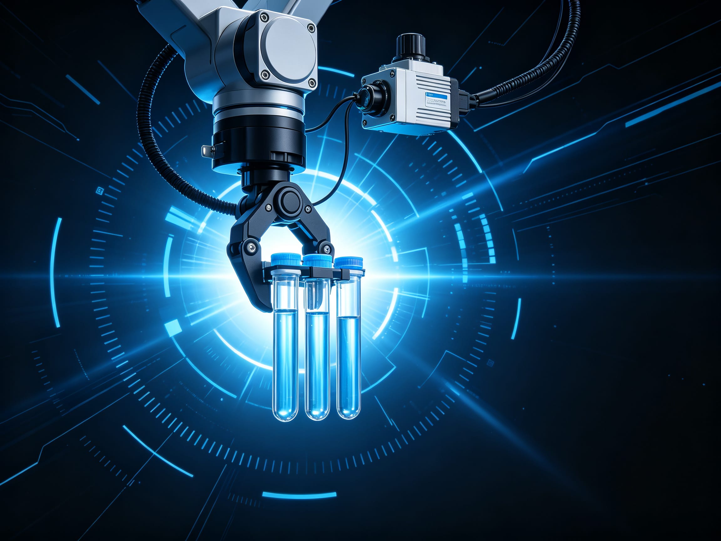
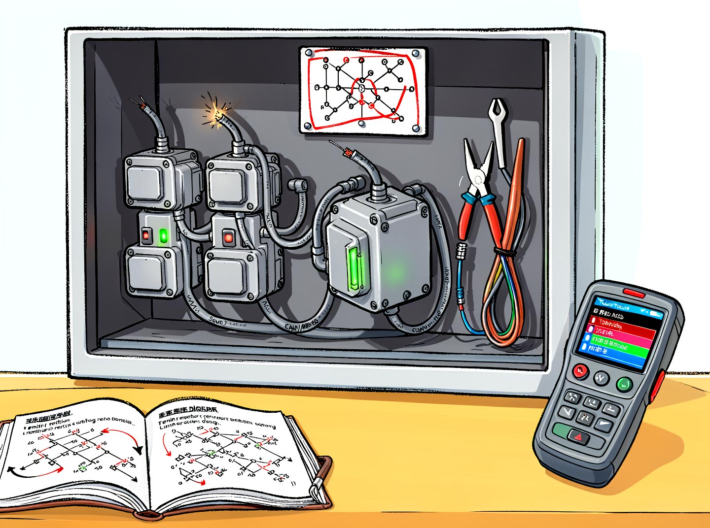
Discover how this product is applied across various industrial automation scenarios.


Compatible Products
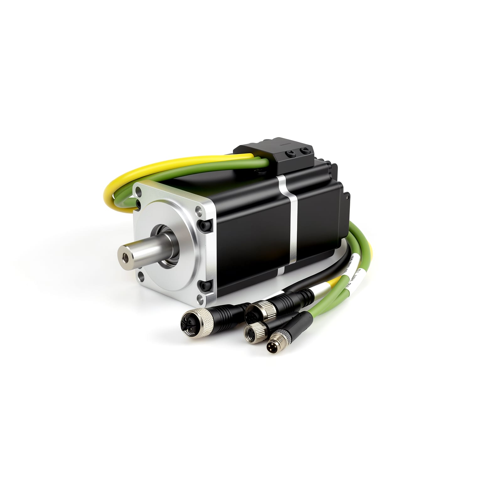
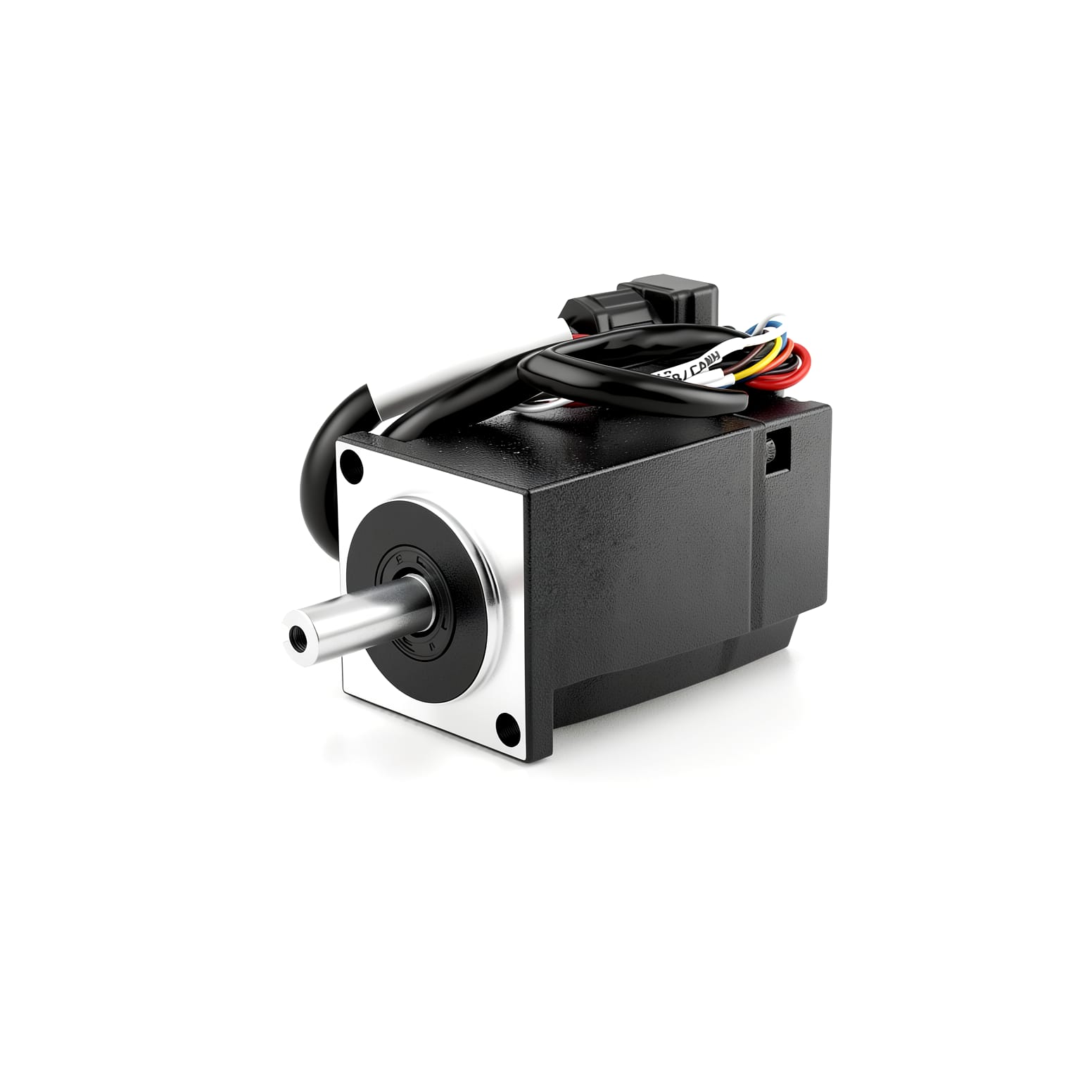
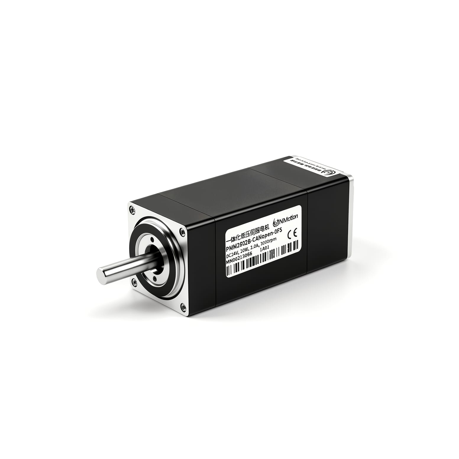
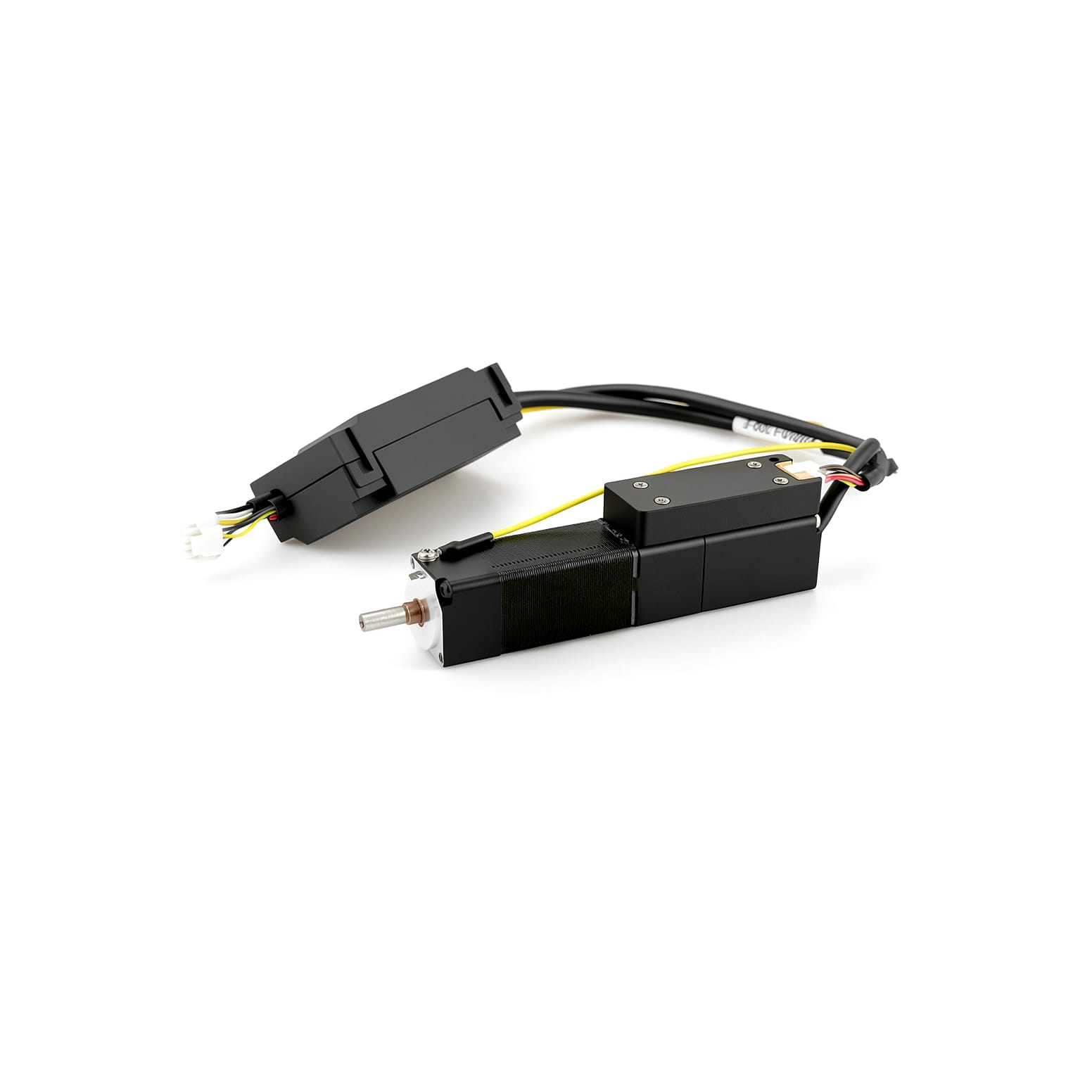
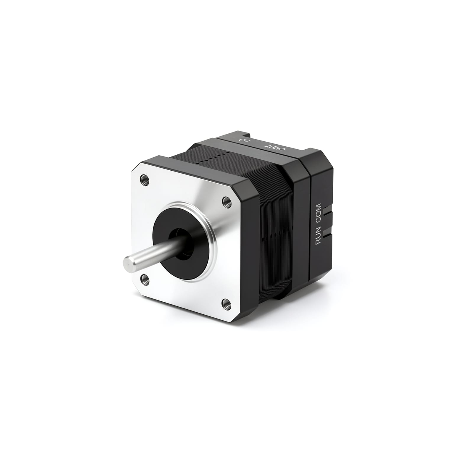
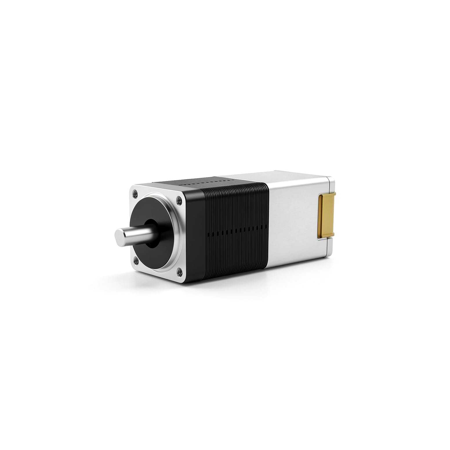
Build complete and reliable solutions with our compatible products.
Technical Resources
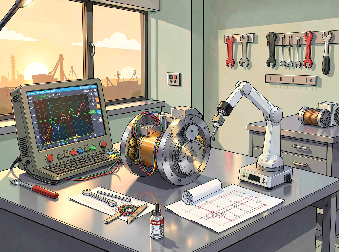
Technical guides, application notes, and more to help you get the most out of the product.
Ready to start your automation project?
Talk to our engineers and get a customized motion control solution within 24 hours.
Typical response time: 24 hours